


30 ASUS P2B-D2 User’s Manual
Connectors
III. INSTALLATION
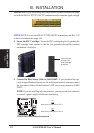
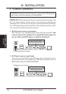
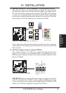
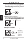
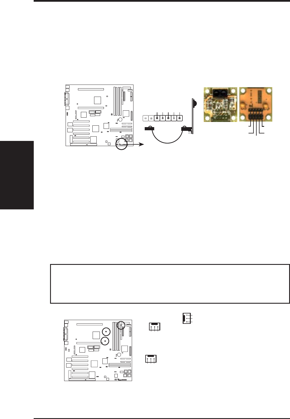
11. IrDA-Compliant infrared module connector (5 pin IR)
This connector supports the optional wireless transmitting and receiving infrared
module. This module mounts to a small opening on system cases that support this
feature. You must also configure the setting through “UART2 Use Infrared” in
Chipset Features Setup to select whether UART2 is directed for use with COM2
or IrDA. Use the five pins as shown on the Back View and connect a ribbon cable
from the module to the motherboard according to the pin definitions.
Front View
P2B-D2 Infrared Module Connector
For the infrared feature to be available,
you must connect the optional Infrared
(IrDA) module to the motherboard
+5V
IRTX
IRRX
(NC)
GND
Back View
IRTX
IRRX
+5V
GND
(NC)
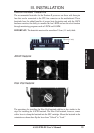
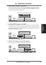
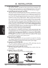
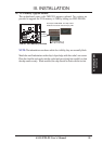
12. Chassis, CPU, & Power Supply Fan Connectors (3 pin FAN)
These connectors support cooling fans of 500mA (6W) or less. Orientate the
fans so that the heat sink fins allow airflow to go across the onboard heatsink(s)
instead of the expansion slots. Depending on the fan manufacturer, the wiring
and plug may be different. The red wire should be positive, while the black
should be ground. Connect the fan’s plug to the board taking into consideration
the polarity of the this connector.
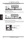
NOTE: The “Rotation” signal must only be used with fans specially designed
with rotation signal.
WARNING! The CPU and/or motherboard will overheat if there is no airflow
across the CPU and onboard heatsinks. Damage may occur to the motherboard
and/or the CPU fan if these pins are incorrectly used. These are not jumpers,
do not place jumper caps over these pins.
P2B-D2 12Volt Cooling Fan Power
Chassis
Fan Power
CPU Fan Power
Power Supply
Fan Power
Ground
Rotation
+12V
Ground
Rotation
+12V
Ground
Rotation
+12V
III. INSTALLATION
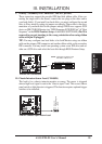
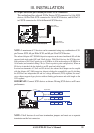
NOTE: If you are install-
ing two processors, you
may connect the fan from
the second heatsink to ei-
ther the power supply or
chassis fan connector.