


ASUS P2B-D/P2B-DS User’s Manual 11
III. INSTALLATION
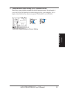
Jumpers
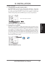
1) CLRTC p. 13 Clear Real Time Clock (RTC) RAM
2) KBPWR p. 13 Keyboard Power Up (Enable/Disable)
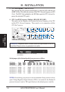
3) FS0, FS1, FS2 p. 14 CPU Bus Frequency
4) CF1, CF2, CF3, CF4 p. 14 CPU Core:Bus Frequency Multiple
5) JP18 p. 15 Chassis Intrusion Sensor Setting (Enable/Disable)
Expansion Slots/Sockets
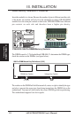
1) DIMM Sockets p. 18 DIMM Memory Support
2) SEC CPU Slot p. 19 Single Edge Contact CPU Support
3) SLOT1, SLOT2 p. 24 16-bit ISA Bus Expansion Slots
*
4) PCI1, PCI2, PCI3, PCI4 p. 25 32-bit PCI Bus Expansion Slots
†
5) AGP p. 25 Accelerated Graphics Port
Hardware Monitor
1) JP4, JP5 p. 22 CPU heat Sensor Connector (O/R)
Connectors
1) PS2KBMS p. 26 PS/2 Keyboard Connector (6-pin female)
2) PS2KBMS p. 26 PS/2 Mouse Connector (6-pin female)
3) PRINTER p. 27 Parallel (Printer) Port Connector (25-pin female)
4) COM1/COM2 p. 27 Serial Port COM1/COM2 (two 9-pin male)
5) FLOPPY p. 27 Floppy Drive Connector (34-1 pins)
6) USB p. 28 Universal Serial BUS Ports 1 & 2 (two 4-pin female)
7) Primary/Secondary IDE p. 28 Primary/Secondary IDE Connector (40 pins)
8) IDELED p. 29 IDE/SCSI LED Activity Light (2 pins)
9) CHA_/CPU_/PWR_FAN p. 29 Chassis/CPU/Power Supply Fan Connectors (3-pin block)
10) IR p. 30 Infrared Port Module Connector (5 pins)
11) ATXPWR p. 30 ATX Motherboard Power Connector (20 pins)
12) WOLCON p. 31 Wake-On-LAN Connector (3 pins)
13) CHASSIS p. 31 Chassis Intrusion Sensor Lead (4-1 pins) (O/R)
14) MSG.LED (PANEL) p. 32 LED Lead (2 pins)
15) SMI (PANEL) p. 32 SMI Suspend Switch Lead (2 pins)
16) PWR.SW (PANEL) p. 32 ATX Power Switch / Soft Power Switch (2 pins)
17) RESET (PANEL) p. 32 Reset Switch Lead (2 pins)
18)
PWR.LED (
PANEL
)
p. 32 System Power LED (3 pins)
19)
KEYLOCK (
PANEL
)
p. 32 Keyboard Lock Switch Lead (2 pins)
20) SPEAKER (PANEL) p. 32 Speaker Connector (4 pins)
21) SCSI-50/SCSI-68/ULTRA2-68 p. 33 Ultra-Fast (50-)/-Wide (68-)/Ultra2 (68-pin) SCSI Connectors
22) DMA_HEADER p. 34 SB-LINK™ Connector (6-1 pins) (O/R)
23) SMB p. 34 SMBus Connector (3 pins) (O/R)
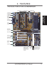
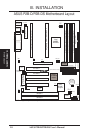
Board Layout
III. INSTALLATION
*
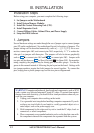
The onboard hardware monitor uses the address 290H-297H so legacy ISA cards must not use this
address, otherwise conflicts will occur.
O/R: Optional/Reserved for future use.