


ASUS P2B-D/P2B-DS User’s Manual 17
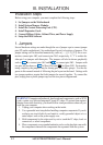
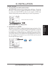
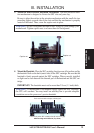
2. System Memory (DIMM)
This motherboard uses only Dual Inline Memory Modules (DIMMs). Three sockets
are available for 3.3Volt (power level) unbuffered Synchronous Dynamic Random
Access Memory (SDRAM) of either 8, 16, 32, 64, 128, or 256MB to form a memory
size between 8MB and 1GB. One side (with memory chips) of the DIMM takes up
one row on the motherboard.
To utilize the chipset’s Error Checking and Correction (ECC) feature, you must use a
DIMM module with 9 chips per side (standard 8 chips/side + 1 ECC chip) and make
the proper settings through “Chipset Features Setup” in IV. BIOS SOFTWARE.
Memory speed setup is recommended through SDRAM Configuration under “Chipset
Features Setup”.
IMPORTANT (see General DIMM Notes below)
• SDRAMs used must be compatible with the current Intel PC100 SDRAM
specification.
III. INSTALLATION
III. INSTALLATION
System Memory
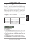
Install memory in any combination as follows:
DIMM Location 168-pin DIMM Memory Modules Total Memory
Socket 1 (Rows 0&1) SDRAM 8, 16, 32, 64, 128, 256MB x1
Socket 2 (Rows 2&3) SDRAM 8, 16, 32, 64, 128, 256MB x1
Socket 3 (Rows 4&5) SDRAM 8, 16, 32, 64, 128, 256MB x1
Socket 4 (Rows 6&7) SDRAM 8, 16, 32, 64, 128, 256MB x1
Total System Memory (Max 1GB) =
General DIMM Notes
• Use only PC100-compliant DIMMs. This motherboard operates at 100MHz, thus most
systems will not even boot if non-compliant modules are used because of the strict tim-
ing issues involved under this speed.
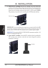
• Two possible memory chips are supported: SDRAM with and without ECC.
• SDRAM chips are generally thinner with higher pin density than EDO (Extended Data
Output) chips.
• BIOS shows SDRAM memory on bootup screen.
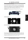
• 8 chips/side modules do not support ECC, only 9 chips/side modules support ECC.
• Single-sided DIMMs come in 16, 32, 64, 128MB; double-sided come in 32, 64, 128, 256MB.
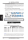
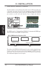
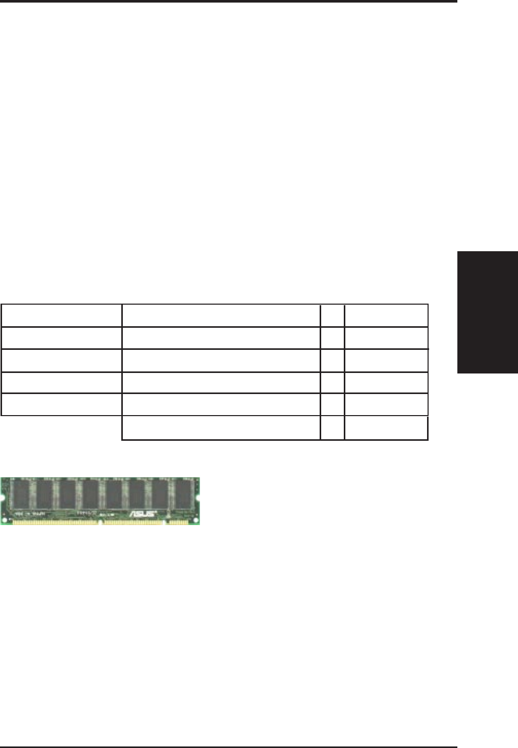
ASUS Memory Example:
SDRAM DIMM (8 chips, Non-ECC)