


ASUS P2L-VM/P2E-VM User’s Manual 13
III. INSTALLATION
Jumpers
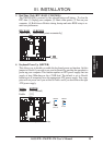
1) INT_EN p. 14 VGA Interrupt Setting (Enable/Disable)
2) VGAEN p. 14 VGA Setting (Enable/Disable)
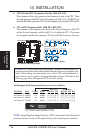
3) CLRCMOS p. 15 Real Time Clock RAM (Clear CMOS)
4) KBPWR p. 15 Keyboard Power Up (Enable/Disable)
5) FS0, FS1, FS2 p. 16 CPU External Clock (BUS) Frequency Selection
6) BF0, BF1, BF2, BF3 p. 16 CPU:BUS Frequency Ratio
Expansion Slots
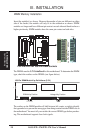
1) DIMM Sockets p. 17 168-Pin DIMM Memory Support
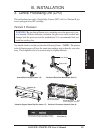
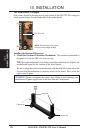
2) SEC CPU Slot p. 19 Single Edge Contact CPU Support
3) ISA Slot 1, 2 p. 25 16-bit ISA Bus Expansion Slots
*
4) PCI Slot 1, 2, 3 p. 25 32-bit PCI Bus Expansion Slots
Hardware Monitor
1) RTCPU p. 22 CPU Thermal Sensor Connector
Connectors
1) KEYBOARD p. 26 PS/2 Keyboard Connector (6-pin Female)
2) MOUSE P. 26 PS/2 Mouse Connector (6-pin Female)
3) PRINTER p. 27 Parallel Port Connector (25-pin Female)
4) COM1 p. 27 Serial Port COM1 Connector (9-pin Male)
5) VGA p. 27 Monitor (VGA) Output Connector (15 pin female)
6) AUDIO (optional) p. 28 Audio Port Connectors (Three 1/8” Female) (optional)
7) GAME (optional) p. 28 Joystick/Midi Connector (15-pin Female) (optional)
8) USB p. 29 Universal Serial BUS Ports 1 & 2 (Two 4-pin Female)
9) PRIMARY/SECONDARY IDE p. 29 Primary/Secondary IDE Connectors (Two 40-1pins)
10) IDELED p. 29 IDE LED Activity Light (2 pins)
11) FLOPPY p. 30 Floppy Disk Drive Connector (34-1pins)
12) CD1/CD2/AUX (optional) p. 30 Stereo Audio In Connectors (Three 4 pins)
13) SPDIF (optional) p. 30 Digital Audio Interface (6 pins)
14) IR p. 31 IrDA-Compliant Infrared Module Connector (5 pins)
15) WOL_CON p. 31 Wake on LAN Connector (3-pins)
16) LED (PANEL) p. 32 System Message LED (2 pins)
17) SMI (PANEL) p. 32 SMI Switch Lead (2 pins)
18) PWR (PANEL) p. 32 ATX Power & Soft-Off Switch Lead (2 pins)
19) RESET (PANEL) p. 32 Reset Switch Lead (2 pins)
20)
KEYLOCK (
PANEL
)
p. 32 System Power LED Lead (3 pins)
21)
KEYLOCK (
PANEL
)
p. 32 Keyboard Lock Switch Lead (2 pins)
22) SPEAKER (PANEL) p. 32 Speaker Output Connector (4 pins)
23) CHA_, CPU_, PWR_FAN p. 33 Chassis, CPU, Power Supply Fan Connectors (Three 3-pin)
24) ATXPWR p. 33 ATX Power Supply Connector (20 pins)
25) CTL_CON p. 33 Power Supply Fan Connector (6 pins)
26) COM2 p. 34 Serial Port COM2 Connector (10-1 pins)
27) TV_CON (optional) p. 34 TV-Out Connector for External TV-Out Bracket (6-1 pins)
*
The onboard hardware monitor uses the address 290H-297H so legacy ISA cards
must not use this address; otherwise, conflicts will occur.
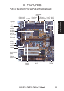
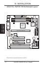
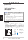
Motherboard Layout
III. INSTALLATION