


30 ASUS P2L-VM/P2E-VM User’s Manual
III. INSTALLATION
Connectors
III. INSTALLATION
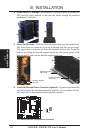
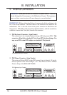
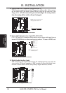
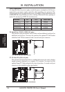
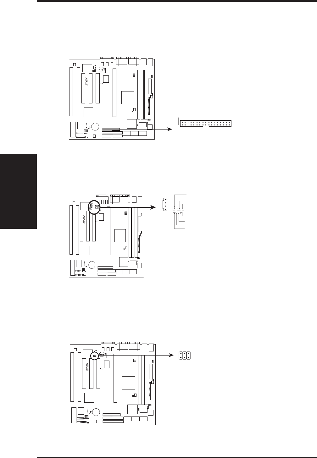
11. Floppy Disk Drive Connector (34-1pin FLOPPY)
This connector supports the provided floppy drive ribbon cable. After connect-
ing the single end to the board, connect the two plugs on the other end to the
floppy drives. (Pin 5 is removed to prevent inserting in the wrong orienta-
tion when using ribbon cables with pin 5 plugged).
R
P2L-VM/P2E-VM Floppy Disk Drive Connector
NOTE: Orient the red markings on
the floppy ribbon cable to
PIN 1
PIN 1
Floppy Disk Drive Connector
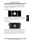
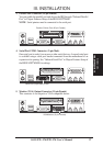
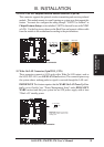
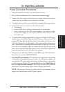
12. Stereo Audio In Connectors (4-pin CD1, CD2, AUX)
CD1, CD2, and AUX connectors can be used to receive stereo audio input from an
internal CD-ROM drive or other sound sources such as a TV tuner or MPEG card.
R
P2L-VM/P2E-VM Stereo Audio In Connectors
NOTE: AUX has the same pin
definitions as CD1
AUX
CD1
CD2
Left Audio Channel
Right Audio Channel
Ground
Ground
Right Audio Channel
Left Audio Channel
Ground
Ground
L
G
G
R
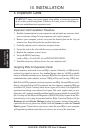
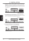
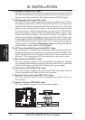
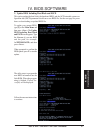
13. Digital Audio Interface (6-pin)
This connector is the digital link between the motherboard and your audio de-
vices such as CD player, sampler, or DAT recorder. It allows the digital trans-
mission of audio data in SPDIF (Sony/Philips Digital Interface) Format.
R
P2L-VM/P2E-VM Digital Audio Interface
TTL: Short this, if output device is TTL level
SPDIFO: Digital Signal OUT
SPDIFI: Digital Signal IN
SPDIF