


ASUS P3B-1394 User’s Manual 35
3. HARDWARE SETUP
Connectors
3. H/W SETUP
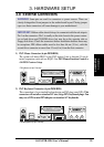
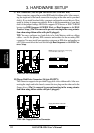
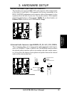
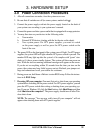
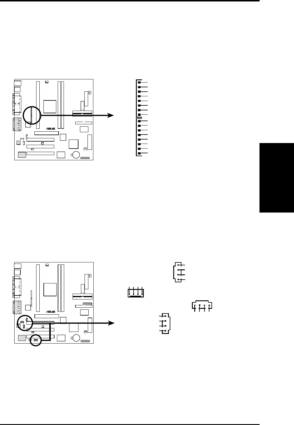
14) IEEE-1394 Headers (8-pin 1394HEAD2/1394HEAD3)
These headers can support an IEEE-1394 serial connector cable set that mounts
to the front of a case with a 1394 connector slot for easy accessibility or an
IEEE-1394/COM2 combination serial connector cable set that mounts to a free
expansion slot at the back of your case. You can also connect 1394-compliant
internal fixed-disk drives to these headers. NOTE: To use these headers, set
Onboard 1394 to Enabled (see 4.7 PNP and PCI Setup)
P3B-1394
®
P3B-1394 IEEE-1394 Headers
1394HEAD3 1394HEAD2
Ground
Ground
TPA2+
TPA2-
TPB2-
TPB2+
Ground
+12V
Ground
Ground
TPA2+
TPA2-
TPB2-
TPB2+
Ground
+12V
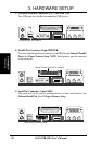
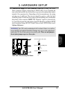
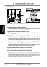
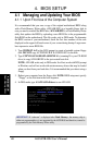
15) Internal Audio Connectors (4-pin MODEM, CD_IN, AUX_CON, VIDEO)
These connectors allow you to receive stereo audio input from sound sources,
such as a CD-ROM, TV tuner, or MPEG card. The MODEM connector allows
the onboard audio to interface with a voice modem card with a similar connec-
tor. It also allows the sharing of microphone and speaker between the onboard
audio and the voice modem card.
P3B-1394
®
P3B-1394 Internal Audio Connectors
CD_IN
Right Audio Channel
Left Audio Channel
Ground
Ground
MODEM
Ground
Modem-Out
Ground
AUX_CON
Right Audio Channel
Left Audio Channel
Ground
Ground
Modem-In
VIDEO
Right Audio Channel
Left Audio Channel
Ground
Ground