


36 ASUS P3B-1394 User’s Manual
Connectors
3. H/W SETUP
3. HARDWARE SETUP
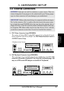
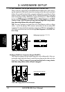
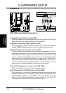
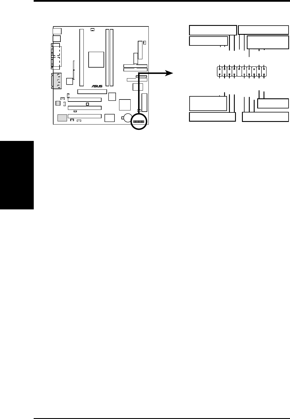
16) System Message LED Lead (2-pin MLED)
The LED connected to this lead indicates the state of the system. The LED lights
when the system is in suspend mode and is OFF otherwise.
17) Keyboard Lock Switch Lead (2-pin KEYLOCK)
This 2-pin connector connects to the case-mounted key switch to allow keyboard
locking. NOTE: When the keyboard is locked, the mouse can still be used.
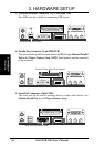
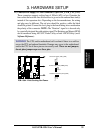
18) System Management Interrupt Lead (2-pin SMI)
This allows the user to manually place the system into a suspend mode or “Green”
mode where system activity will be instantly decreased to save electricity and
expand the life of certain components when the system is not in use. This 2-pin
connector (see the preceding figure) connects to the case-mounted suspend switch.
If you do not have a switch for the connector, you may use the “Turbo Switch”
since it does not have a function. SMI is activated when it detects a short to open
moment and therefore leaving it shorted will not cause any problems. This may
require one or two pushes depending on the position of the switch.
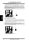
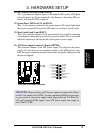
19) System Warning Speaker Connector (4-pin SPEAKER)
This 4-pin connector connects to the case-mounted speaker.
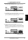
20) ATX Power Switch / Soft-Off Switch Lead (2-pin PWR)
The system power is controlled by a momentary switch connected to this lead.
Pushing the button once will switch the system between ON and SLEEP or ON
and SOFT OFF, depending on your BIOS or OS setting. Pushing the switch
while in the ON mode for more than 4 seconds will turn the system off. The
system power LED shows the status of the system’s power.
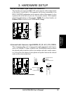
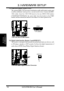
P3B-1394
®
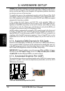
P3B-1394 System Panel Connections
*
Requires an ATX power supply.
IDELED-
Keylock
+5V
Speaker
Speaker
Connector
Power LED
Ground
Reset SW
IDELED
Message LED
ExtSMI#
Reset Ground
Ground
Keyboard Lock
ATX Power
Switch*
PWRBTN
Ground
IDELED+
PWRLED+
PWRLED-
PWRLEDB-
MSGLED+
MSGLED-
Ground
SMI Lead
For items 16-23