


ASUS P5P800ASUS P5P800
ASUS P5P800ASUS P5P800
ASUS P5P800
2-132-13
2-132-13
2-13
2.4 System memory
2.4.12.4.1
2.4.12.4.1
2.4.1
OverviewOverview
OverviewOverview
Overview
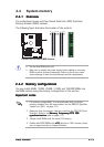
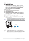
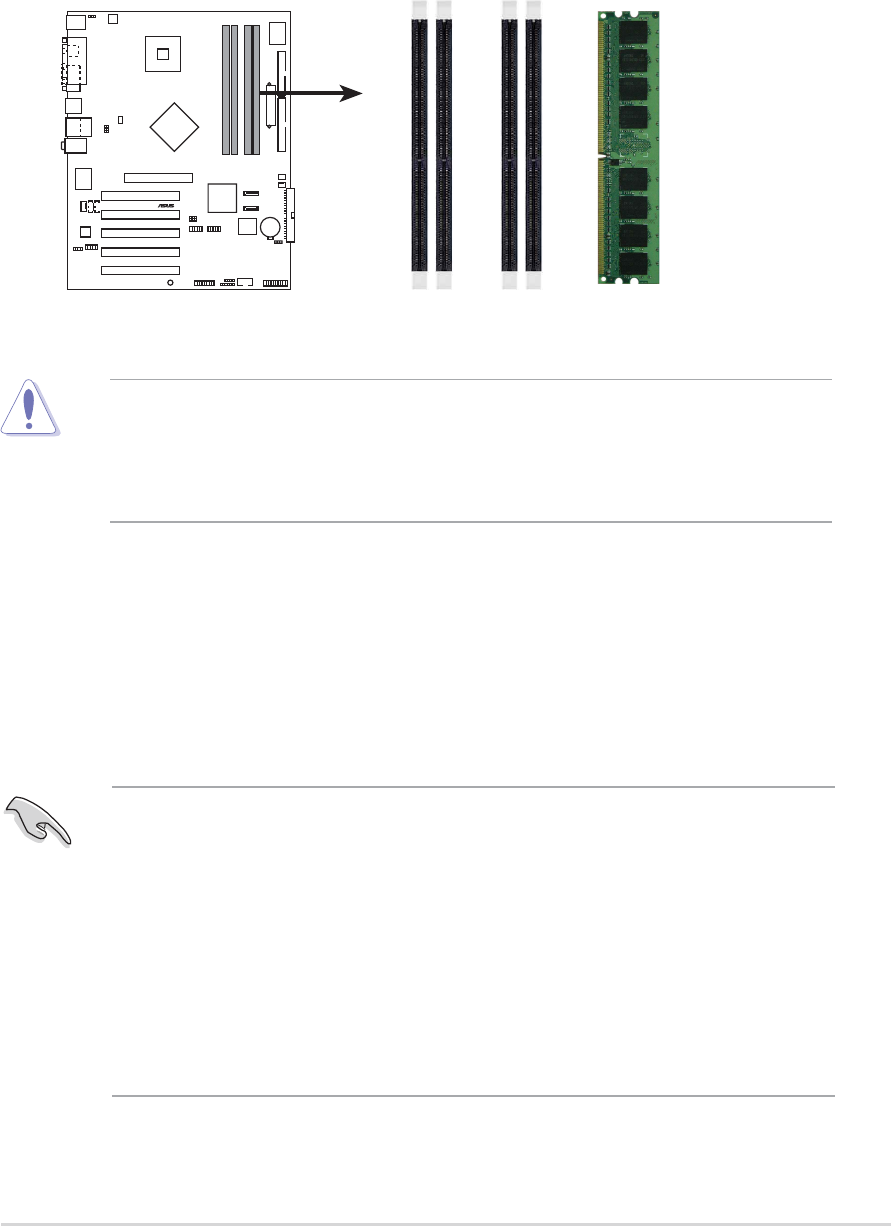
The motherboard comes with four Double Data Rate (DDR) Dual Inline
Memory Modules (DIMM) sockets.
The following figure illustrates the location of the sockets:
P5P800
®
P5P800 184-Pin DDR DIMM Sockets
DIMM_A1
DIMM_A2
DIMM_B1
DIMM_B2
2.4.22.4.2
2.4.22.4.2
2.4.2
Memory configurationsMemory configurations
Memory configurationsMemory configurations
Memory configurations
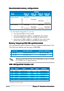
You may install 64MB, 128MB, 256MB, 512MB, and 1GB DDR DIMMs into
the DIMM sockets using the memory configurations in this section.
Important notesImportant notes
Important notesImportant notes
Important notes
• Use the blue DIMM slots first.
• Make sure to unplug the power supply before adding or removing
DIMMs or other system components. Failure to do so may cause
severe damage to both the motherboard and the components.
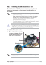
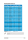
1. For optimum compatibility, it is recommended that you obtain
memory modules from the same vendor. See the DDR400 Qualified
Vendor List (QVL) on page 2-14.
2. Make sure that the memory frequency matches the CPU FSB (Front
Side Bus). Refer to the
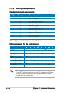
Memory frequency/CPU FSBMemory frequency/CPU FSB
Memory frequency/CPU FSBMemory frequency/CPU FSB
Memory frequency/CPU FSB
synchronizationsynchronization
synchronizationsynchronization
synchronization table on page 2-14.
3. Always install DIMMs with the same CAS Latency.
4. Double-sided DDR DIMMs with
x16x16
x16x16
x16 (data bus=16bit) memory chips
are not supported due to chipset limitation.