


2-302-30
2-302-30
2-30
Chapter 2: Hardware informationChapter 2: Hardware information
Chapter 2: Hardware informationChapter 2: Hardware information
Chapter 2: Hardware information
8.8.
8.8.
8.
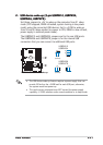
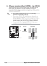
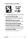
ATX power connectors (24-pin EATXPWR,ATX power connectors (24-pin EATXPWR,
ATX power connectors (24-pin EATXPWR,ATX power connectors (24-pin EATXPWR,
ATX power connectors (24-pin EATXPWR,
4-pin ATX12V)4-pin ATX12V)
4-pin ATX12V)4-pin ATX12V)
4-pin ATX12V)
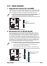
These connectors are for an ATX power supply. The plugs from the
power supply are designed to fit these connectors in only one
orientation. Find the proper orientation and push down firmly until the
connectors completely fit.
P5P800
®
P5P800 ATX power connector
EATXPWRATX12V
+3 Volts
+3 Volts
Ground
+5 Volts
+5 Volts
Ground
Ground
Power OK
+5V Standby
+12 Volts
-5 Volts
+5 Volts
+3 Volts
-12 Volts
Ground
Ground
Ground
PSON#
Ground
+5 Volts
+12 Volts
+3 Volts
+5 Volts
Ground
+12V DC GND
+12V DC GND
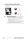
•
Do not forget to connect the 4-pin ATX +12 V power plug;
otherwise, the system will not boot up.
• When using an ATX 12 V PSU with 20-pin power plug, make sure
that it can provide 8 A on the +12 V lead and at least 1A on the
+5V standby lead (+5 VSB). The minimum recommended wattage is
300 W, or 350 W for a fully configured system. The system may
become unstable or may not boot up if the power is inadequate.
• You must install a Power Supply Unit (PSU) with a higher power
rating if you intend to install additional devices.