


2-322-32
2-322-32
2-32
Chapter 2: Hardware informationChapter 2: Hardware information
Chapter 2: Hardware informationChapter 2: Hardware information
Chapter 2: Hardware information
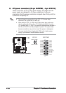
11.11.
11.11.
11.
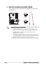
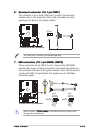
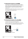
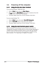
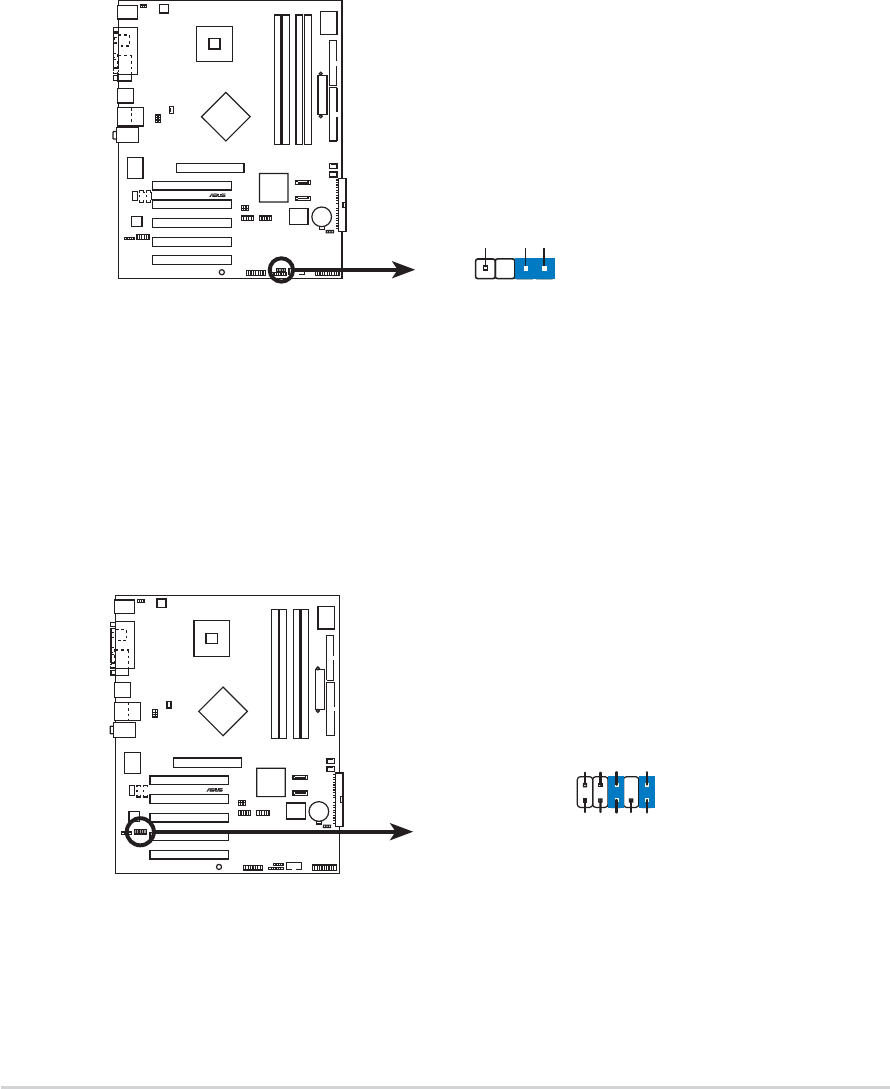
Chassis intrusion connector (4-1 pin CHASSIS)Chassis intrusion connector (4-1 pin CHASSIS)
Chassis intrusion connector (4-1 pin CHASSIS)Chassis intrusion connector (4-1 pin CHASSIS)
Chassis intrusion connector (4-1 pin CHASSIS)
This connector is for a chassis-mounted intrusion detection sensor or
switch. Connect one end of the chassis intrusion sensor or switch
cable to this connector. The chassis intrusion sensor or switch sends a
high-level signal to this connector when a chassis component is
removed or replaced. The signal is then generated as a chassis
intrusion event.
By default, the pins labeled “Chassis Signal” and “Ground” are shorted
with a jumper cap. Remove the jumper caps only when you intend to
use the chassis intrusion detection feature.
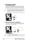
12.12.
12.12.
12.
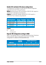
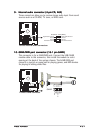
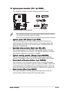
Front panel audio connector (10-1 pin FP_AUDIO)Front panel audio connector (10-1 pin FP_AUDIO)
Front panel audio connector (10-1 pin FP_AUDIO)Front panel audio connector (10-1 pin FP_AUDIO)
Front panel audio connector (10-1 pin FP_AUDIO)
This is an interface for the front panel audio cable that allows
convenient connection and control of audio devices.
By default, the pins labeled LINE_OUT_R/BLINE_OUT_R and the pins
LINE_OUT_L/BLINE_OUT_L are shorted with jumper caps. Remove the
caps only when you are connecting the front panel audio cable.
P5P800
®
P5P800 intrusion connector
CHASSIS
+5VSB_MB
Chassis Signal
GND
(Default)
P5P800
®
P5P800 Front Panel Audio Connector
FP_AUDIO
BLINE_OUT_L
MIC2
Line out_R
Line out_L
BLINE_OUT_R
NC
MICPWR
+5VA
AGND