


2-282-28
2-282-28
2-28
Chapter 2: Hardware informationChapter 2: Hardware information
Chapter 2: Hardware informationChapter 2: Hardware information
Chapter 2: Hardware information
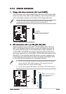
4.4.
4.4.
4.
CPU and Chassis fan connectorsCPU and Chassis fan connectors
CPU and Chassis fan connectorsCPU and Chassis fan connectors
CPU and Chassis fan connectors
(4-pin CPU_FAN, CHA_FAN)(4-pin CPU_FAN, CHA_FAN)
(4-pin CPU_FAN, CHA_FAN)(4-pin CPU_FAN, CHA_FAN)
(4-pin CPU_FAN, CHA_FAN)
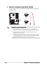
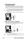
The fan connectors support cooling fans of 350mA~2000mA (24 W
max.) or a total of 1A~3.48A (41.76 W max.) at +12V. Connect the
fan cables to the fan connectors on the motherboard, making sure that
the black wire of each cable matches the ground pin of the connector.
Do not forget to connect the fan cables to the fan connectors. Lack of
sufficient air flow inside the system may damage the motherboard
components. These are not jumpers! DO NOT place jumper caps on the
fan connectors!
P5P800
®
P5P800 Fan connectors
CPU_FAN
CHA_FAN
GND
Rotation
+12V
GND
CPU FAN PWR
CPU FAN IN
CPU FAN PWM
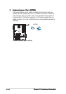
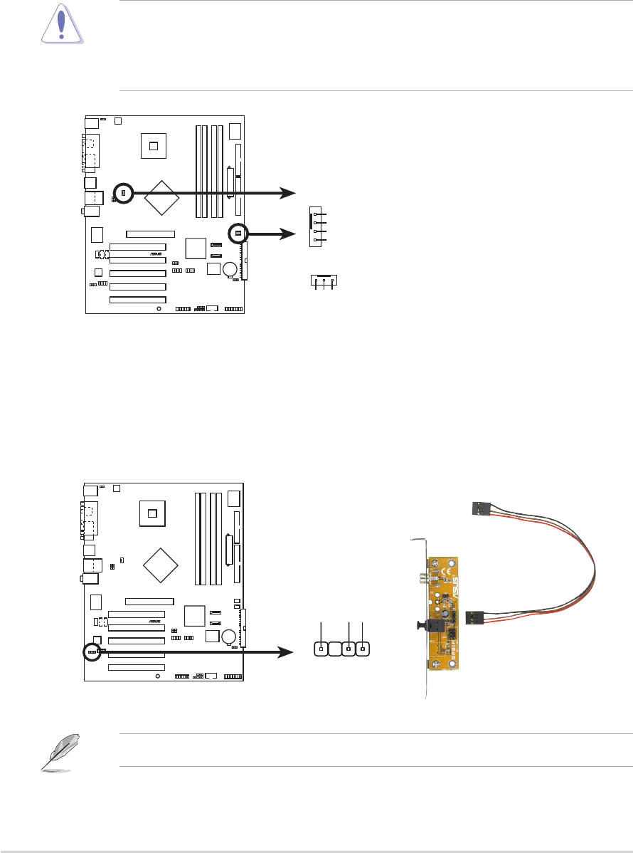
5.5.
5.5.
5.
Digital audio connector (4-1 pin SPDIF_OUT)Digital audio connector (4-1 pin SPDIF_OUT)
Digital audio connector (4-1 pin SPDIF_OUT)Digital audio connector (4-1 pin SPDIF_OUT)
Digital audio connector (4-1 pin SPDIF_OUT)
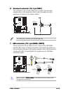
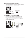
This connector is for the S/PDIF audio module to allow digital sound
output. Connect one end of the S/PDIF audio cable to this connector
and the other end to the S/PDIF module.
The S/PDIF module is purchased separately.
P5P800
®
P5P800 Digital audio connector
+5V
SPDIFOUT
GND
SPDIF_OUT