


ASUS P5P800SASUS P5P800S
ASUS P5P800SASUS P5P800S
ASUS P5P800S
1-291-29
1-291-29
1-29
6.6.
6.6.
6.
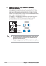
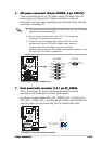
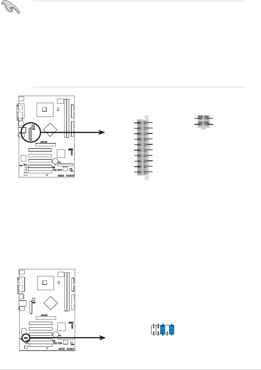
ATX power connectors (20-pin ATXPWR, 4-pin ATX12V)ATX power connectors (20-pin ATXPWR, 4-pin ATX12V)
ATX power connectors (20-pin ATXPWR, 4-pin ATX12V)ATX power connectors (20-pin ATXPWR, 4-pin ATX12V)
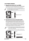
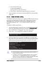
ATX power connectors (20-pin ATXPWR, 4-pin ATX12V)
These connectors are for an ATX power supply. The plugs from the
power supply are designed to fit these connectors in only one
orientation. Find the proper orientation and push down firmly until the
connectors completely fit.
•
You can also use a Power Supply Unit (PSU) with a 24-pin ATX power
connector on this motherboard.
•
Do not forget to connect the 4-pin ATX +12 V power plug;
otherwise, the system will not boot up.
• Use a PSU with a minimum power rating of 300 W on this
motherboard. Use of a PSU with a higher power output is
recommended when configuring a system with more
power-consuming devices. The system may become unstable or may
not boot up if the power is inadequate.
P5P800S
®
P5P800S ATX power connectors
ATXPWR
Pin 1
+3.3VDC
-12.0VDC
COM
PS_ON#
COM
COM
COM
-5.0VDC
+5.0VDC
+5.0VDC
PWR_OK
+12.0VDC
+3.3VDC
+3.3VDC
COM
+5.0VDC
COM
+5.0VDC
COM
+5VSB
ATX12V
+12V DC
GND
+12V DC
GND
7.7.
7.7.
7.
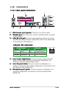
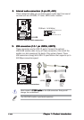
Front panel audio connector (10-1 pin FP_AUDIO)Front panel audio connector (10-1 pin FP_AUDIO)
Front panel audio connector (10-1 pin FP_AUDIO)Front panel audio connector (10-1 pin FP_AUDIO)
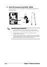
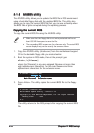
Front panel audio connector (10-1 pin FP_AUDIO)
This is an interface for the front panel audio cable that allows
convenient connection and control of audio devices.
By default, the pins labeled LINE_OUT_R/BLINE_OUT_R and the pins
LINE_OUT_L/BLINE_OUT_L are shorted with jumper caps. Remove the
caps only when you are connecting the front panel audio cable.
P5P800S
®
P5P800S Front panel audio connector
FP_AUDIO
BLINE_OUT_L
MIC2
Line out_R
Line out_L
BLINE_OUT_R
NC
MICPWR
+5VA
AGND