


ASUS P5P800SASUS P5P800S
ASUS P5P800SASUS P5P800S
ASUS P5P800S
1-311-31
1-311-31
1-31
10.10.
10.10.
10.
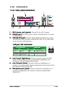
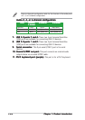
GAME/MIDI port connector (16-1 pin GAME)GAME/MIDI port connector (16-1 pin GAME)
GAME/MIDI port connector (16-1 pin GAME)GAME/MIDI port connector (16-1 pin GAME)
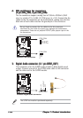
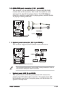
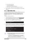
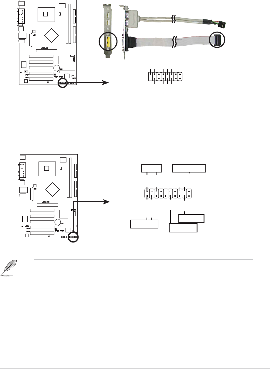
GAME/MIDI port connector (16-1 pin GAME)
This connector is for a GAME/MIDI port. Connect the USB/GAME
module cable to this connector, then install the module to a slot
opening at the back of the system chassis. The GAME/MIDI port
connects a joystick or game pad for playing games, and MIDI devices
for playing or editing audio files.
P5P800S
®
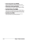
P5P800S Game connector
GAME
+5V
+5V
J2B1
J2CX
MIDI_OUT
J2CY
J2B2
MIDI_IN
J1B1
J1CX
GND
GND
J1CY
J1B2
+5V
11.11.
11.11.
11.
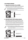
System panel connector (20-1 pin PANEL)System panel connector (20-1 pin PANEL)
System panel connector (20-1 pin PANEL)System panel connector (20-1 pin PANEL)
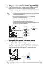
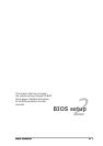
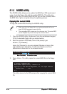
System panel connector (20-1 pin PANEL)
This connector supports several chassis-mounted functions.
The sytem panel connector is color-coded for easy connection. Refer to
the connector description below for details.
P5P800S
®
P5P800S System Panel connector
*
Requires an ATX power supply.
PLED-
PWR
+5V
Speaker
PLED
Ground
RESET
Ground
Reset
Ground
Ground
PLED+
IDE_LED-
IDE_LED+
IDE_LED
SPEAKER
PWRSW
PANEL
•
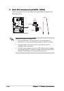
System power LED (3-pin PLED)System power LED (3-pin PLED)
System power LED (3-pin PLED)System power LED (3-pin PLED)
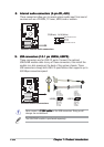
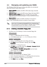
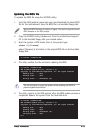
System power LED (3-pin PLED)
This 3-pin connector is for the system power LED. Connect the
chassis power LED cable to this connector. The system power LED
lights up when you turn on the system power, and blinks when the
system is in sleep mode.