


ASUS P5VD2-MX/P5V-VM DHASUS P5VD2-MX/P5V-VM DH
ASUS P5VD2-MX/P5V-VM DHASUS P5VD2-MX/P5V-VM DH
ASUS P5VD2-MX/P5V-VM DH
1-291-29
1-291-29
1-29
2.2.
2.2.
2.
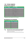
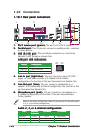
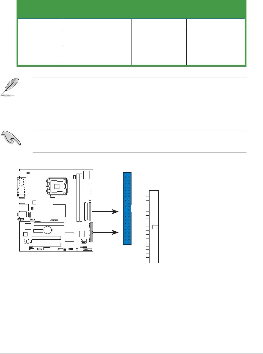
Primary/Secondary IDE connectors (40-1 pin PRI_IDEPrimary/Secondary IDE connectors (40-1 pin PRI_IDE
Primary/Secondary IDE connectors (40-1 pin PRI_IDEPrimary/Secondary IDE connectors (40-1 pin PRI_IDE
Primary/Secondary IDE connectors (40-1 pin PRI_IDE
[blue]; 40-1 pin SEC_IDE [black])[blue]; 40-1 pin SEC_IDE [black])
[blue]; 40-1 pin SEC_IDE [black])[blue]; 40-1 pin SEC_IDE [black])
[blue]; 40-1 pin SEC_IDE [black])
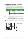
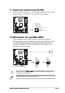
The onboard IDE connectors are for Ultra DMA 133/100/66 signal
cables. There are three connectors on each Ultra DMA 133/100/66
signal cable: blue, black, and gray. Connect the blue connector to the
motherboard's IDE connector, then select one of the following modes
to configure your device(s).
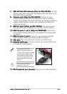
• Pin 20 on the IDE connector is removed to match the covered hole
on the Ultra DMA cable connector. This prevents incorrect insertion
when you connect the IDE cable.
• Use the 80-conductor IDE cable for Ultra DMA 100/66 IDE devices.
Black or gray
Drive jumperDrive jumper
Drive jumperDrive jumper
Drive jumper
ModeMode
ModeMode
Mode
CableCable
CableCable
Cable
settingsetting
settingsetting
setting
of device(s)of device(s)
of device(s)of device(s)
of device(s)
connectorconnector
connectorconnector
connector
Single device Cable-Select or Master - Black
Two devices Cable-Select Master Black
Slave Gray
Master Master
Slave Slave
®
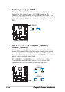
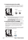
IDE connectors
NOTE: Orient the red markings
(usually zigzag) on the IDE
ribbon cable to PIN 1.
SEC_IDE
PIN 1
PRI_IDE
If any device jumper is set as "Cable-Select," make sure all other device
jumpers have the same setting.