


1-321-32
1-321-32
1-32
Chapter 1: Product introductionChapter 1: Product introduction
Chapter 1: Product introductionChapter 1: Product introduction
Chapter 1: Product introduction
7.7.
7.7.
7.
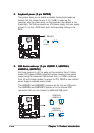
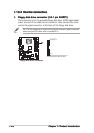
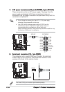
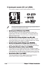
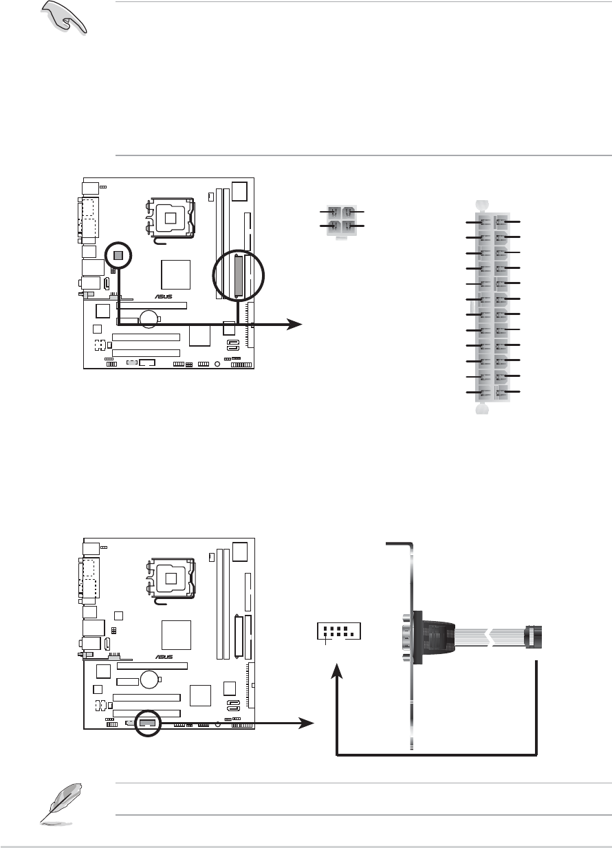
ATX power connectors (24-pin EATXPWR,ATX power connectors (24-pin EATXPWR,
ATX power connectors (24-pin EATXPWR,ATX power connectors (24-pin EATXPWR,
ATX power connectors (24-pin EATXPWR,
4-pin ATX12V)4-pin ATX12V)
4-pin ATX12V)4-pin ATX12V)
4-pin ATX12V)
These connectors are for an ATX power supply. The plugs from the
power supply are designed to fit these connectors in only one
orientation. Find the proper orientation and push down firmly until the
connectors completely fit.
•
Do not forget to connect the 4-pin ATX +12 V power plug;
otherwise, the system will not boot up.
• Use a PSU with a minimum power rating of 300 W on this
motherboard. Use of a PSU with a higher power output is
recommended when configuring a system with more
power-consuming devices. The system may become unstable or may
not boot up if the power is inadequate.
8.8.
8.8.
8.
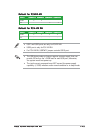
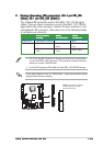
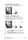
Serial port connector (10-1 pin COM2)Serial port connector (10-1 pin COM2)
Serial port connector (10-1 pin COM2)Serial port connector (10-1 pin COM2)
Serial port connector (10-1 pin COM2)
This connector is for a serial (COM) port. Connect the serial port
module cable to this connector, then install the module to a slot
opening at the back of the system chassis.
The Serial (COM) port module is purchased separately.
®
ATX power connectors
EATXPWR
ATX12V
+12V DC
GND
+12V DC
GND
+3 Volts
+3 Volts
Ground
+5 Volts
+5 Volts
Ground
Ground
Power OK
+5V Standby
+12 Volts
-5 Volts
+5 Volts
+3 Volts
-12 Volts
Ground
Ground
Ground
PSON#
Ground
+5 Volts
+12 Volts
+3 Volts
+5 Volts
Ground
®
COM port connector
PIN 1
COM2