


20 ASUS P/I-AP55TV User’s Manual
III. INSTALLATION
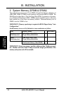
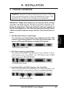
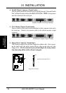
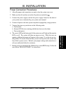
4. Parallel Printer Connector (25-pin Female)
You can enable the parallel port and choose the IRQ through "Onboard Parallel
Port" in Chipset Features Setup of the BIOS SOFTWARE. NOTE: Serial printers
must be connected to the serial port.
Parallel (Printer) Port (25-pin Female)
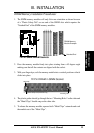
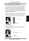
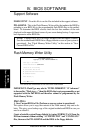
5. VGA Monitor Output (15-pin Female)
These is a built-in video chip on this motherboard so that a separate video card is
not necessary. Connect your monitor cable to the onboard monitor output
connector.
VGA Monitor Output (15-pin Female)
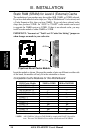
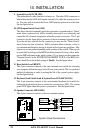
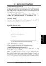
6. Floppy Drive Connector (34-pin block )
This connector supports the provided floppy drive ribbon cable. After connect-
ing the single end to the board, connect the two plugs on the other end to the
floppy drives. (Pin 5 is removed to prevent inserting in the wrong orienta-
tion when using ribbon cables with pin 5 plugged).
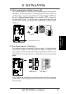
Floppy Drive Connector
Pin 1
Connect the Red stripe to Pin 1
(Connectors)
III. INSTALLATION