


ASUS P/I-AP55TV User’s Manual 23
III. INSTALLATION
(Connectors)
III. INSTALLATION
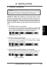
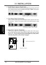
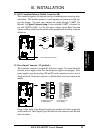
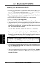
14. IrDA-Compliant Infrared Module Connector (IR)
This connector supports the optional wireless transmitting and receiving infra-
red module. This module mounts to a small opening on system cases that sup-
port this feature. You must also configure the setting through "UART2 Use
Infrared" in Chipset Features Setup to select whether UART2 is directed for
use with COM2 or IrDA. Use the five pins as shown on the Back View and
connect a ribbon cable from the module to the motherboard according to the pin
definitions.
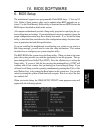
Infrared Module Connector
F
ront
Vi
ew
+5V
IRTX
IRRX
NC
GND
Back View
IRRX
+5V
IRTX
NC
GND
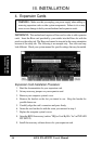
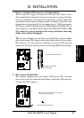
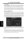
15. Power Input Connector (12-pin block)
This connector connects to a standard 5 Volt power supply. To connect the leads
from the power supply, ensure first that the power supply is not plugged. Most
power supplies provide two plugs (P8 and P9), each containing six wires, two of
which are black. Orient the connectors so that the black wires are located in the
middle.
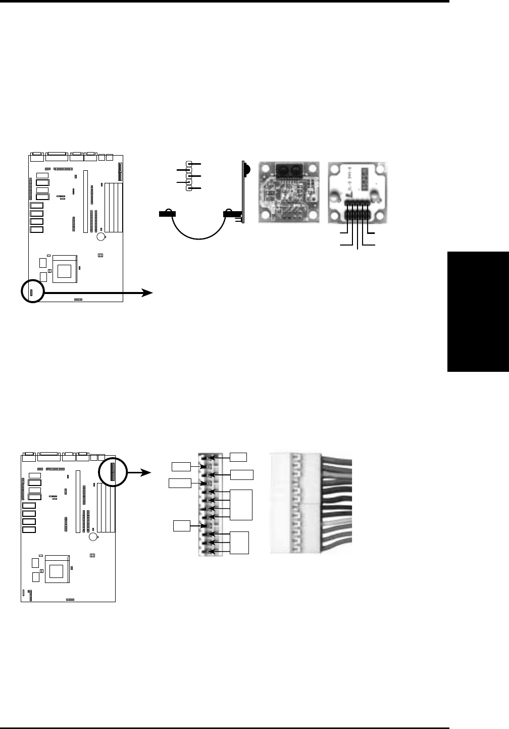
AT Power Connector
on Motherboard
Power Plugs from
Power Supply
-12V
-5V
+12V
+5V
PG
GND
+5V
P9
P8
ORG
RED
YLW
BLU
BLK
BLK
BLK
BLK
WHT
RED
RED
RED
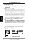
Using a slight angle, align the plastic guide pins on the lead to their receptacles
on the connector. Once aligned, press the lead onto the connector until the lead
locks into place.