


4-64-6
4-64-6
4-6
Chapter 4: Motherboard infoChapter 4: Motherboard info
Chapter 4: Motherboard infoChapter 4: Motherboard info
Chapter 4: Motherboard info
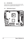
4.4.
4.4.
4.
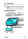
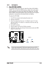
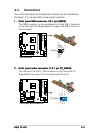
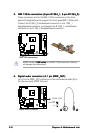
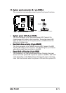
Digital audio connector (4-1 pin SPDIF_OUT)Digital audio connector (4-1 pin SPDIF_OUT)
Digital audio connector (4-1 pin SPDIF_OUT)Digital audio connector (4-1 pin SPDIF_OUT)
Digital audio connector (4-1 pin SPDIF_OUT)
(A) is for the SPDIF_OUT connector on the motherboard while (B) is
for the rear panel S/PDIF Out port.
3.3.
3.3.
3.
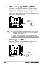
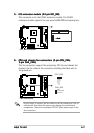
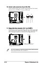
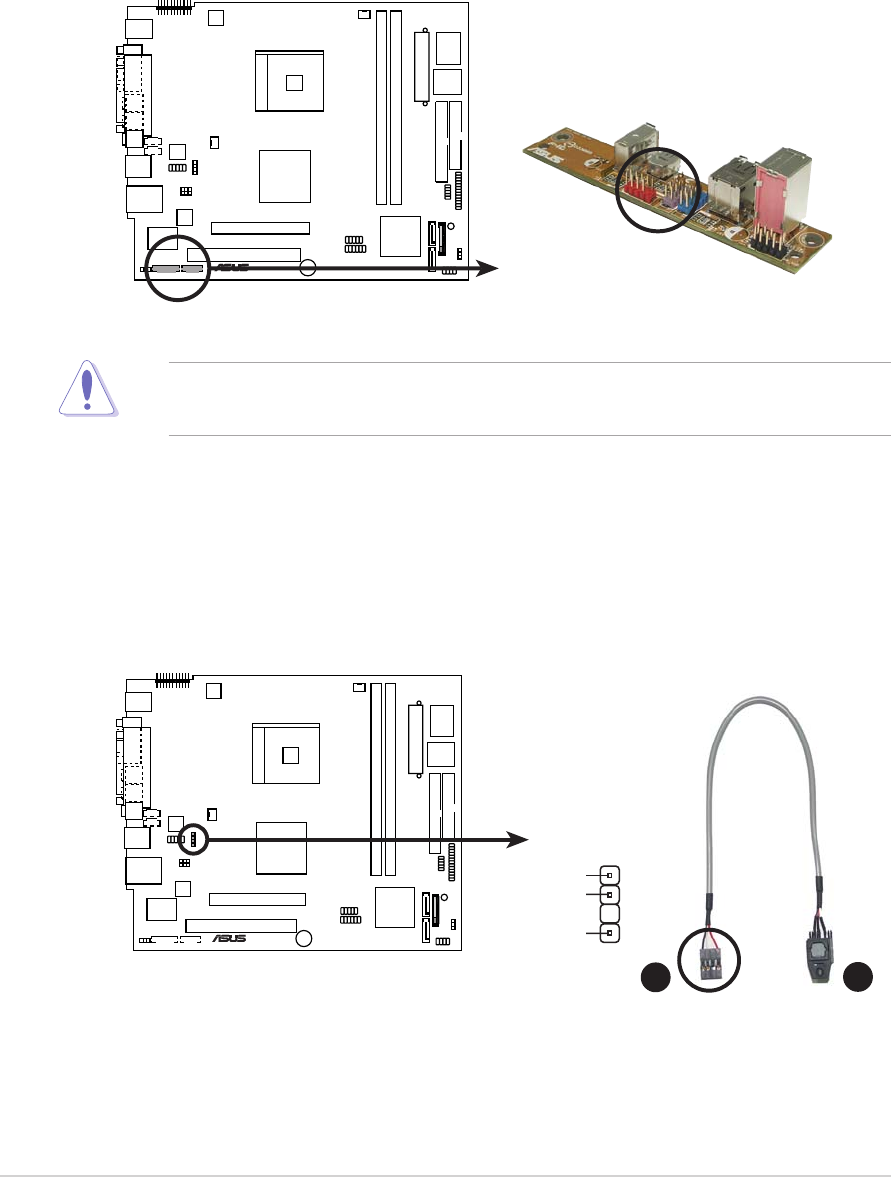
IEEE 1394a connectors (6-pin IE13IEEE 1394a connectors (6-pin IE13
IEEE 1394a connectors (6-pin IE13IEEE 1394a connectors (6-pin IE13
IEEE 1394a connectors (6-pin IE13
94_1, 8-pin IE1394_0)94_1, 8-pin IE1394_0)
94_1, 8-pin IE1394_0)94_1, 8-pin IE1394_0)
94_1, 8-pin IE1394_0)
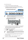
These connectors are for the IEEE 1394a connectors on the front
panel I/O daughterboard to support the front panel IEEE 1394a ports.
Connect the IE1394_0 motherboard connector to the 1394_1
daughterboard connector, and connect the IE1394_1 motherboard
connector to the 1394_2 daughterboard connector.
NEVER connect a
USB cable USB cable
USB cable USB cable
USB cable to the IEEE 1394a connector. Doing so
will damage the motherboard!
®
IEEE 1394 connectors
®
Digital audio connector
+5V
SPDIFOUT
GND
SPDIF_OUT
A
B