


36
Chapter 2: Basic installation
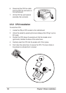
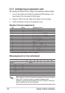
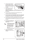
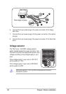
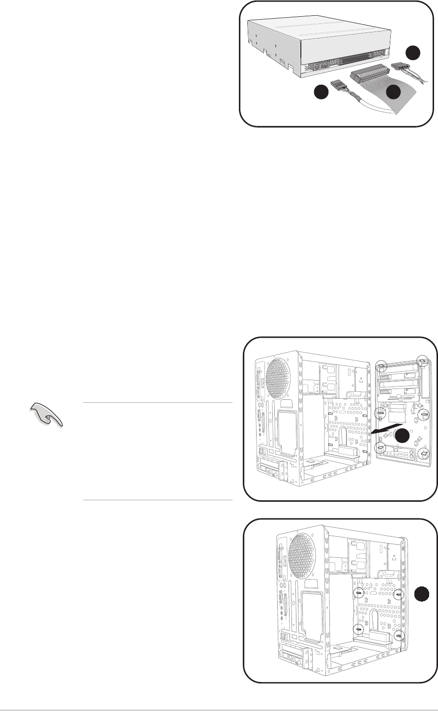
8. Connect a power cable from
the power supply unit to the
power connector at the back of
the optical drive. See page 40
for details.
9. Connect one end of the IDE
ribbon cable to the IDE
interface at the back of the
optical drive, matching the red stripe on the cable with Pin 1 on the
IDE interface.
10. Connect one end of the optical drive audio cable to the 4-pin
connector at the back of the optical drive.
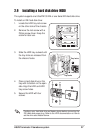
11. Connect the other end of the IDE ribbon cable to the secondary IDE
connector (black connector labeled SEC_IDE) on the motherboard.
See page 82 for the location of the secondary IDE connector.
12. Connect the other end of the audio cable to the 4-pin CD1 connector
on the motherboard. See page 84 for the location of the CD audio
connector.
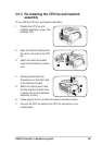
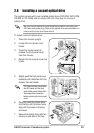
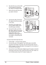
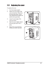
13. Re-install the front panel cover
by aligning its hooks with the
chassis holes.
8
910
14. Lock the front panel cover
hooks to the chassis holes as
indicated.
13
14
On Deluxe models, re-connect
the LED panel and the front
audio button panel cables to
their respective connectors
before re-installing the front
panel cover.