


1-61-6
1-61-6
1-6
Chapter 1: System introductionChapter 1: System introduction
Chapter 1: System introductionChapter 1: System introduction
Chapter 1: System introduction
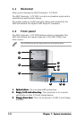
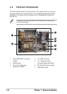
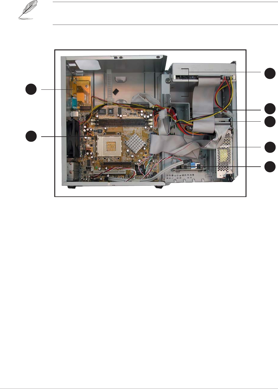
1.4 Internal components
The figure below shows the internal view of the system when you remove
the cover and flip out the drive frame. The standard components already
installed in the system and the locations of the available drive bays are
pointed out.
The system may come with either a PFC (Power Factor Correction) or
non-PFC power supply.
4. 3.5” HDD drive bay
5. 3.5” floppy drive bay
(Optional floppy disk drive)
6. PFC/Non-PFC power supply
7. USB/audio board
1. Game/MIDI/COM1 extension
module
2. Motherboard
3. Two 5.25” drive bays
(Optional CD-ROM)
11
11
1
22
22
2
33
33
3
77
77
7
66
66
6
44
44
4
55
55
5