


2-162-16
2-162-16
2-16
Chapter 2: Basic installationChapter 2: Basic installation
Chapter 2: Basic installationChapter 2: Basic installation
Chapter 2: Basic installation
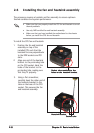
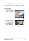
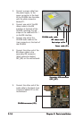
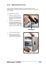
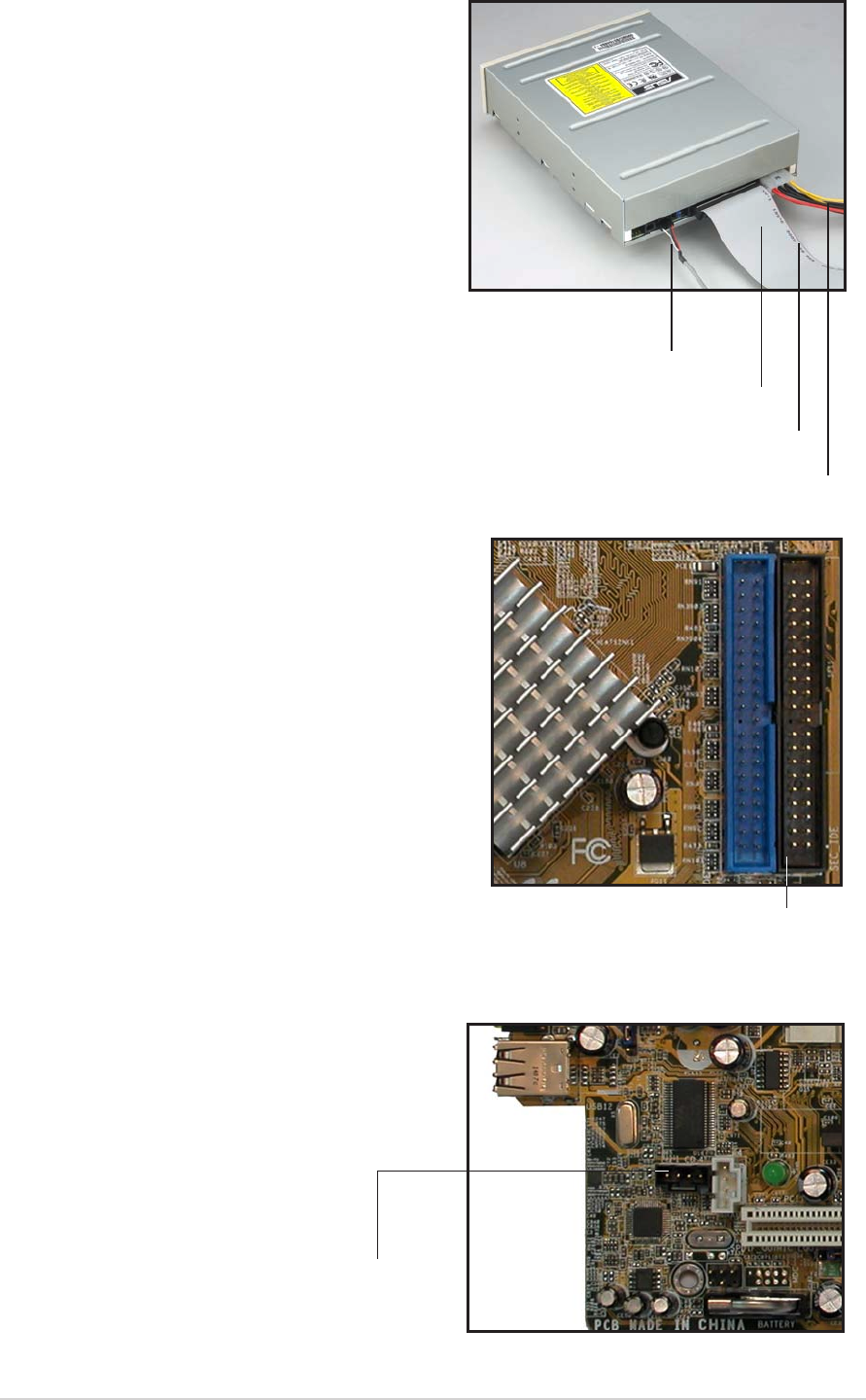
5. Connect a power cable from
the power supply to the
power connector at the back
of the CD-ROM. Use the cable
with the white connector
labeled P1.
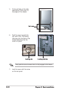
6. Connect one end of the IDE
ribbon cable to the IDE
interface at the back of the
CD-ROM, matching the red
stripe on the cable with Pin 1
on the IDE interface.
7. Connect one end of the
CD-ROM audio cable to the
4-pin connector at the back of
the CD-ROM.
Red stripe to Pin 1Red stripe to Pin 1
Red stripe to Pin 1Red stripe to Pin 1
Red stripe to Pin 1
IDE ribbon cableIDE ribbon cable
IDE ribbon cableIDE ribbon cable
IDE ribbon cable
Power cable (P1)Power cable (P1)
Power cable (P1)Power cable (P1)
Power cable (P1)
CD-ROM audio cableCD-ROM audio cable
CD-ROM audio cableCD-ROM audio cable
CD-ROM audio cable
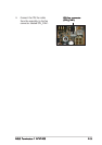
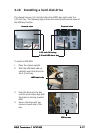
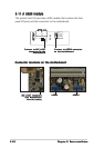
9. Connect the other end of the
audio cable to the black 4-pin
connector labeled CD on the
motherboard.
CD-ROM connector CD-ROM connector
CD-ROM connector CD-ROM connector
CD-ROM connector
(CD)(CD)
(CD)(CD)
(CD)
Secondary IDE connectorSecondary IDE connector
Secondary IDE connectorSecondary IDE connector
Secondary IDE connector
(SEC_IDE)(SEC_IDE)
(SEC_IDE)(SEC_IDE)
(SEC_IDE)
8. Connect the other end of the
IDE ribbon cable to the
secondary IDE connector
(black connector labeled
SEC_IDE) on the motherboard.