


4-84-8
4-84-8
4-8
Chapter 4: Motherboard informationChapter 4: Motherboard information
Chapter 4: Motherboard informationChapter 4: Motherboard information
Chapter 4: Motherboard information
4.4.
4.4.
4.
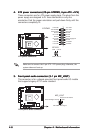
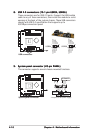
ATX power connectors (20-pin ATXPWR, 4-pin ATX +12V)ATX power connectors (20-pin ATXPWR, 4-pin ATX +12V)
ATX power connectors (20-pin ATXPWR, 4-pin ATX +12V)ATX power connectors (20-pin ATXPWR, 4-pin ATX +12V)
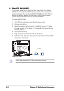
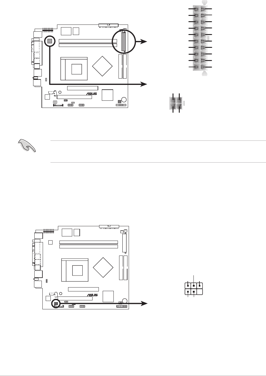
ATX power connectors (20-pin ATXPWR, 4-pin ATX +12V)
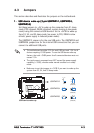
These connectors are for ATX power supply plugs. The plugs from the
power supply are designed to fit these connectors in only one
orientation. Find the proper orientation and push down firmly until the
connectors completely fit.
Make sure to connect the 4-pin ATX +12V power plug; otherwise, the
system does not boot up.
5.5.
5.5.
5.
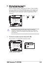
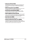
Front panel audio connector (5-1 pin MIC_LOUT)Front panel audio connector (5-1 pin MIC_LOUT)
Front panel audio connector (5-1 pin MIC_LOUT)Front panel audio connector (5-1 pin MIC_LOUT)
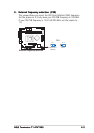
Front panel audio connector (5-1 pin MIC_LOUT)
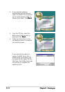
This connector is for a chassis-mounted front panel audio I/O module
that supports legacy AC’97 audio standard.
®
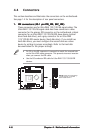
ATX power connector
+3.3Volts
-12.0Volts
Ground
Power Supply O
n
Ground
Ground
Ground
-5.0 Volts
+5.0 Volts
+5.0 Volts
Power Good
+12.0Volts
+3.3 Volts
+3.3 Volts
Ground
+5.0 Volts
Ground
+5.0 Volts
Ground
+5V Standby
ATX12V
ATXPWR
+12V DCCOM
+12V DCCOM
®
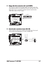
Front panel audio connector
MIC_LOUT
1
MIC SignalMIC PWR
Head set Left channe
l
GNDHead set Right channel
1