


18
4929B–AUTO–01/07
ATA6264 [Preliminary]
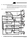
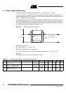
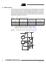
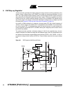
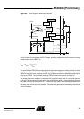
6. Power Supply Sequencing
(Only active when initial programming sets V
VCORE
= 1.88V and V
VPERI
= 3.3V)
In order to meet the requirements of several dual-voltage-supply microcontrollers, a
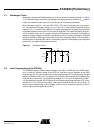
power-sequencing function is implemented. The ATA6264 ensures that the voltage difference
VPERI – VCORE will not exceed 2.8V.
The voltage difference between VPERI and VCORE is monitored. In error cases, for example, if
the VCORE regulator does not start to work, the difference may rise above the 2.8V threshold. In
this case, the VPERI regulator is switched off before reaching this level and switched on again if
the voltage difference drops below a hysteresis value.
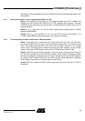
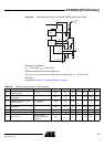
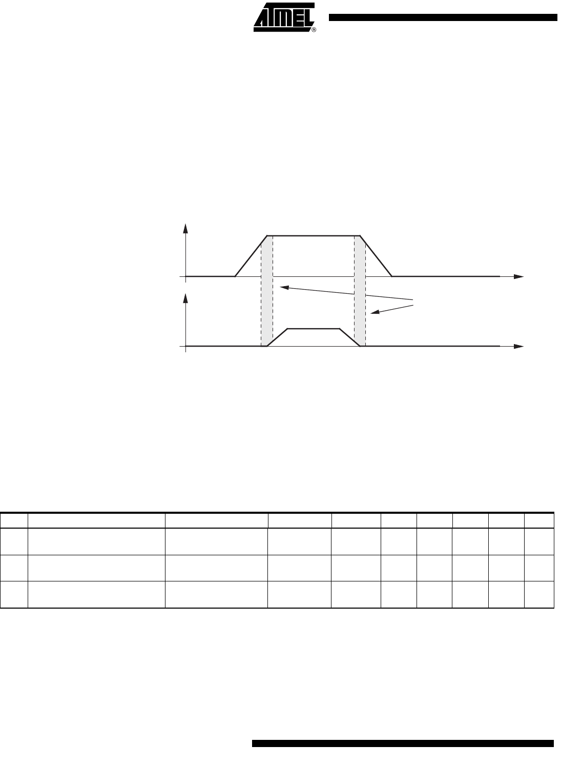
Figure 6-1. Example for Incorrect Ramp Up
Necessary for operation:
V
EVZ
= 0V to 40V, V
INT
= 3.7V to 5.47V
Operating conditions of all other supply pins:
V
K30
, V
VSAT
, V
VPERI
and V
VCORE
are within functional range limits, T
j
= –40°C to 150°C
Other pins:
As defined in Section 4. ”Functional Range” on page 8.
1.88V
Not allowed area:
V
VPERI
- V
VCORE
>
2.8V
3.3V
V
VPERI
V
VCORE
t
t
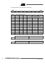
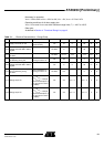
Table 6-1. Electrical Characteristics – Power Supply Sequencing
No. Parameters Test Conditions Pin Symbol Min Typ. Max. Unit Type*
5.1
Maximum voltage difference
V
VPERI
– V
VCORE
VPERI,
VCORE
V
VPERI
– V
VCORE
02.8VA
5.2a
Voltage level V
VPERI
– V
VCORE
to
switch off VPERI regulator
VPERI,
VCORE
V
VPERI
– V
VCORE
2.3 2.8 V A
5.2b
Hysteresis for V
VPERI
– V
VCORE
to
enable VPERI regulator
V
HYS
100 mV A
*) Type means: A = 100% tested, B = 100% correlation tested, C = Characterized on samples, D = Design parameter