


73
4929B–AUTO–01/07
ATA6264 [Preliminary]
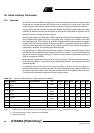
Because the diagnosis commands are non-latching commands, any new serial interface com-
mands, except watchdog triggering (6A55) and the Kx switching commands (9Cxx), interrupt the
diagnosis.
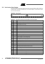
Note: a, b, and c represent the IASG number in binary format; only 001 = IASG1, 010 = IASG2,
011 = IASG3, 100 = IASG4, and 101 = IASG5 are valid commands
Because the IASG commands are non-latching commands, any new serial interface command,
except watchdog triggering (6A55) and the Kx switching commands (9Cxx), interrupts the IASG
function.
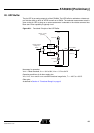
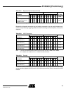
Switch V
VINT
via AMUX to
UZP
1100101011100010 CAE2
Switch voltage at
chip-temperature sensor
via AMUX to UZP
1100101011100100 CAE4
(1)
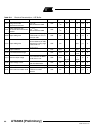
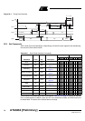
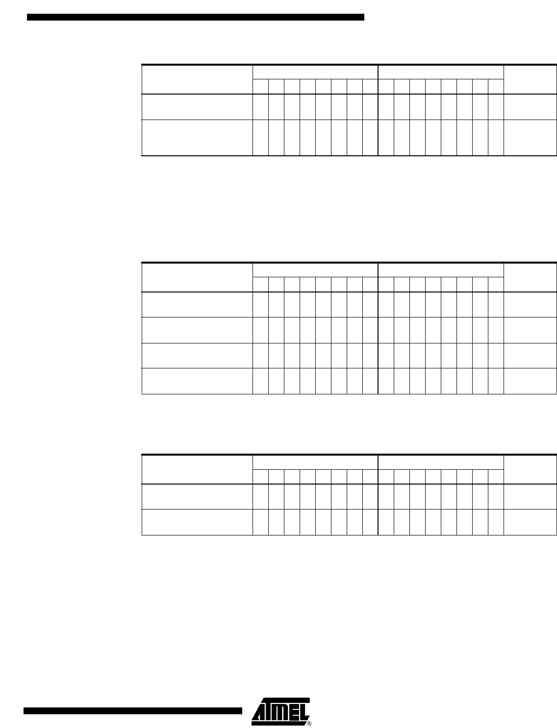
Table 22-8. IASG Commands
Description
MSByte LSByte
Hex Code7654321076543210
IASGx switched to 10V
(mirror factor 10:1)
11110abc00110011 Fx33
IASGx switched to 10V
(mirror factor 15:1)
11110abc00111100 Fx3C
IASGx switched to 5V
(mirror factor 10:1)
11110abc11000011 FxC3
IASGx switched to 5V
(mirror factor15:1)
11110abc11001100 FxCC
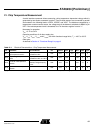
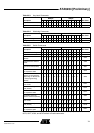
Table 22-9. Example
Description
MSByte LSByte
Hex Code7654321076543210
IASG1 switched to 10V
(mirror factor 10:1)
1111000100110011 F133
IASG5 switched to 5V
(mirror factor 15:1)
1111010111001100 F5CC
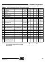
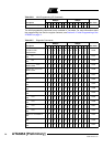
Table 22-7. Diagnosis Commands (Continued)
Description
MSByte LSByte
Hex Code7654321076543210
Note: 1. UZP voltage will be influenced by the USP voltage