


70
4929B–AUTO–01/07
ATA6264 [Preliminary]
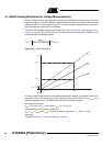
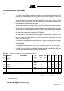
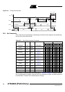
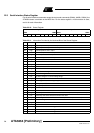
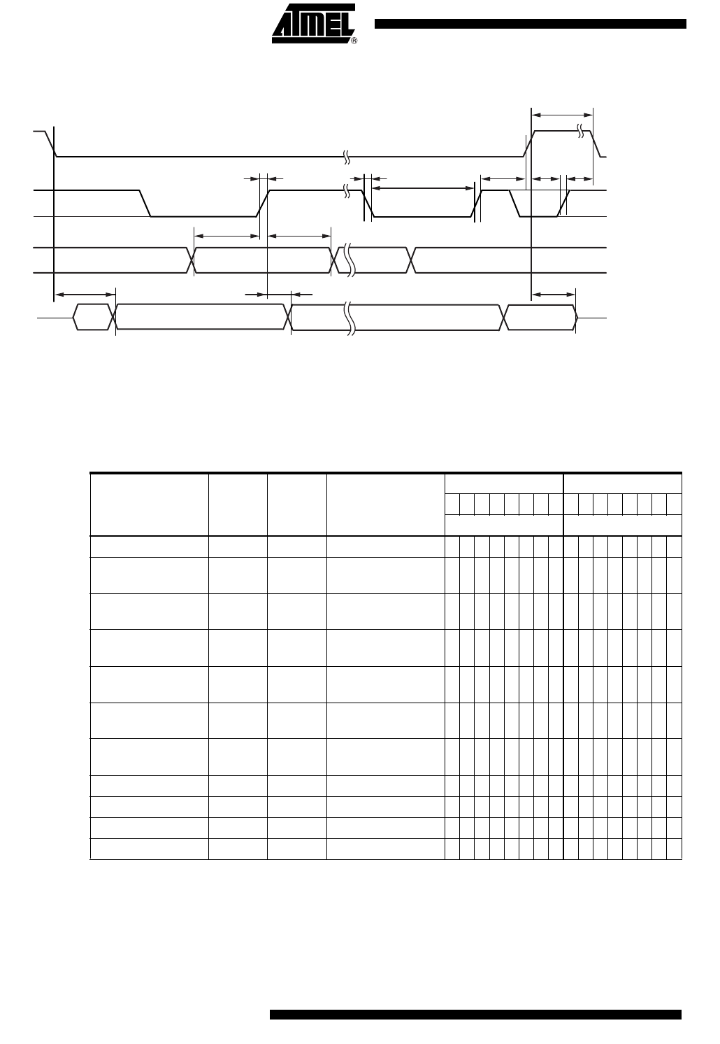
Figure 22-1. Timing Serial Interface
22.2 Set Commands
After a reset due to the watchdog or undervoltage, all internal control registers and decoded sig-
nals are set to their default values.
Serial interface commands other than those listed in Table 22-2 on page 70 lead to an interrup-
tion of measurements via AMUX, cause pin UZP to be switched to tristate, and IASG sources to
be deactivated. The status of the latches does not change.
7. (< 400 ns)
5. (> 20 ns) 6. (> 20 ns)
4. (< 20 ns)
not
defined
not
defined
not defined
LSBMSB
#16#1
LSBMSB
SSQ
SCLK
3. (< 20 ns)
14. (> 40 ns)
8. (< 40 ns)
9. (< 40 ns)
1. (> 100 ns)2. (> 100 ns)
10. (> 1.5 µs)
MISO
MOSI
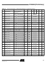
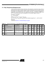
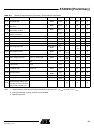
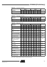
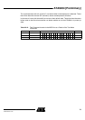
Table 22-2. Set of Serial Interface Commands
Command Latch Hex Description
MSByte LSByte
7654321076543210
Command Option and Data
NOP No 0000 0000000000000000
Key latch Yes 3xxx
See Table 22-3 on
page 71
0011xxxxxxxxxxxx
Watchdog No 6xxx
See Table 22-4 on
page 71
0110xxxxxxxxxxxx
Switch commands Yes 9xxx
See Table 22-5 on
page 71
1001xxxxxxxxxxxx
Initial programming N/A Axxx
See Table 22-6 on
page 72
1010xxxxxxxxxxxx
Diagnosis No Cxxx
See Table 22-7 on
page 72
1100xxxxxxxxxxxx
IASG No Fxxx
See Table 22-8 on
page 73
1111xxxxxxxxxxxx
Test mode 1 No 55AA 0101010110101010
Test mode 2 No AA55 1010101001010101
Test mode 3 No 5500 0101010100000000
Test-mode enable No 5A5A 0101101001011010