


39
4929B–AUTO–01/07
ATA6264 [Preliminary]
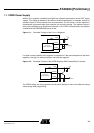
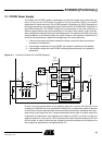
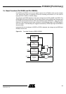
13. USP Comparator for General Purpose
The USP comparator is used for general purposes, for example, low battery detection. An exter-
nal resistive voltage divider provides the input signal for pin USP. A missing USP connection or
V
USP
< 2.44V sets the status register bit b7 to low. During normal operation (V
USP
> 2.44V) the
status register bit b7 stays high.
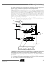
Figure 13-1. Functional Principle of the USP Comparator
Necessary for operation:
V
EVZ
= 5.5V to 40V, V
PERI
> reset threshold, V
CORE
> reset threshold, V
INT
= 3.7V to 5.47V
Operating conditions of all other supply pins:
V
SAT
and V
K30
are within functional range limits, T
j
= –40°C to 150°C
Other pins:
As defined in Section 4. ”Functional Range” on page 8.
Status register
USP
GNDA
to AMUX
2.44V
-
+
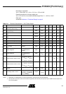
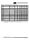
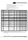
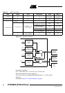
Table 13-1. Electrical Characteristics – USP Comparator for General Purpose
No. Parameters Test Conditions Pin Symbol Min Typ. Max. Unit Type*
12.1 Input current at pin USP V
USP
= 2.44V USP I
USP
–2.5 +2.5 µA A
12.2 Input current at pin USP V
USP
= 0 to 40V USP I
USP
–2.5 +2.5 µA A
12.3 Threshold voltage at pin USP
Trigger voltage for status
register bit 7= high with
increasing V
USP
USP V
USP
2.44 ±5% V A
12.4 De-glitching time t
deglitch
20 60 µs D
*) Type means: A = 100% tested, B = 100% correlation tested, C = Characterized on samples, D = Design parameter