


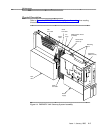
Maintenance
Table 4-2. System States (continued)
AINIT
ASAI Initialization — Displayed when the DEFINITY LAN
Gateway software is initializing from boot.
ASAI-X
ASAI-Ethernet State — Displayed when the DEFINITY LAN
Gateway software is fully initialized and providing service, or
ready to provide service. X indicates the number of DEFINITY
LAN Gateway client connections.
Shutdown States
E_SHUT
Error Shutdown — Flashes whenever a critical error condition is
encountered and the system is shutting down. Once the disk is
spun down, the display becomes steadily lit. Flashware
continues to execute. Can also be entered when:
Board tests have failed and the red LED is lit.
Flashware or software has failed to initialize and has shut
down.
A maintenance shutdown was directed and an operational
error occurs. For instance, the Faceplate and Alarm Panel
(FAC) timed out on the transition of the MFB to the
M_SHUT state.
On a running system, maintenance software detects a
condition requiring an error shutdown.
When in this state, the system can be powered down and
removed from the switch carrier for repair.
M_SHUT
Maintenance Shutdown — Flashes when a technician has
directed Maintenance shutdown either by pressing the
BOOT/SHUTDOWN button, or through the SYSTEM
SHUTDOWN command on a maintenance terminal. Flashware
executes and the disk is spun down. Once the system is
completely shut down, the display becomes steadily lit.
When in this state, the system can be powered down and
removed from the switch carrier for repair.
S_SHUT
Shows only if the interboard bus cable is disconnected.
Reconnecting the cable will bring the system back to the OA&M
or ASAI-E state.
Maintenance, Utility
Status Messages
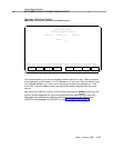
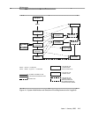
CMD
Displayed when the flashware is running and a technician on a
remote or local maintenance terminal enters the Command
Mode menu. Can be entered in the BTEST, M_SHUT, or
E_SHUT state by pressing
Ctrl C
twice. Menu options
include:
1. Display initialization history — Lists flashware tests that
have passed during system initialization, and other
information.
2. Display status — Lists current alarms, hardware status
diagnostics, sensor and voltage readings, and other
information. These displays are also shown on the
Issue 1 January 1996 4-7