


Installation
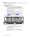
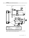
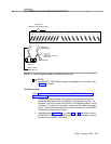
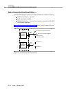
Amphenol Connector
Female RJ45
Female
RS-232
MFB Y-Cable
(H600-352-G1)
ALB Cable
(H600-353-G2)
20 19 18 17 16 15 14 13 12 11 10
5th 4th 3rd 2nd 1st
9 8 7 6 5 4 3 2 1
Example of
DEFINITY LAN Gateway Slots
(not used)
Figure 2-3. Connecting the Adapter Cables Rear-Panel View
NOTE:
If the DEFINITY LAN Gateway system was shipped in a new switch, skip
to Step 7 of this task.
Installation Steps
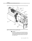
Using Worksheet A-3, Port Slot Locations for the DEFINITY LAN Gateway
System Assembly, follow the steps below to install the system assembly.
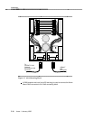
1. Remove any existing cables from the third and fourth slots of the five
contiguous slots reserved for the DEFINITY LAN Gateway system. For
example, if you are to install the DEFINITY LAN Gateway system in slots
7 through 11 of carrier A in the switch, remove the I/O cables from slots 8
and 9. (These are the two slots that provide connectivity to the DEFINITY
LAN Gateway system circuit packs.)
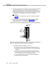
2. Referring back to Figure 2-3 and to Steps 2a and 2b that follow, connect
the DEFINITY LAN Gateway system assembly adapter cables to the port
connectors on the back of the switch.
Issue 1 January 1996 2-9