


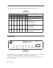
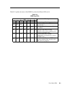


Cables, Connectors, and Ports Table
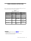
Table A-1 shows the cables, connectors, and ports for installing the RPSD system. This table
includes optional connections as well as the basic configuration.
TABLE A-1
Cables, Connectors, and Ports
Part
COMCODE
From
To
modular connector
XXXXXX
PBX
RJ11 at modem
6 position wire
XXXXXX
RJ11 at PBX
RJ11 at modem
modular connector
1
XXXXXX
Cable from PBX
modem
7 ft. cable with modular
Supplied with
RPSD Lock
CO line or modem
connector on each end
RPSD Lock
14 ft. cable with modular
Supplied with
RPSD Lock
CO line or modem
connector on each end
RPSD Lock
RJ11 wall jack
2
XXXXXX
RJ11 to RPSD
CO line
EIA-RS-232 cable
3
XXXXXX
DB25 at RPSD
DB25 at admin.
Lock
terminal or printer
or A/B switch
DB25 connector
3
XXXXXX
RPSD Lock
Cable to admin.
terminal or printer
or A/B switch
DB25 connector
3
XXXXXX
Admin. terminal or
Cable to RPSD
printer or A/B
Lock
switch
1
The 212A modem uses a DB25 connection. See Figures 2-7 and 2-8 for the details on making up
the appropriate connector.
2
If RJ11 receptacle is not present on CO line, install one.
3
The RPSD Lock maybe connected to the administration terminal, printer, or A/B switch
(to allow connection to both the terminal and printer).
Cables, Connectors, and Ports Table A-1