


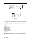


Cables, Connectors, and Ports Table
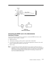
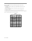
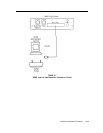
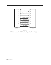
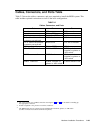
Table 2-2 shows the cables, connectors, and ports required to install the RPSD system. This
table includes optional connections as well as the basic configuration.
TABLE 2-2
Cables, Connectors, and Ports
Part From
To
modular connector
6 position wire
modular connector
1
7 ft. cable with modular
connector on each end
14 ft. cable with modular
connector on each end
RJ11 wall jack
2
EIA-RS-232 cable
3
DB25 connector
3
DB25 connector
3
PBX
RJ11 at PBX
Cable from PBX
RPSD Lock
RPSD Lock
RJ11 to RPSD
DB25 at RPSD Lock
RPSD Lock
Admin. terminal or
printer or A/B switch
RJ11 at modem
RJ11 at modem
modem
CO line or modem
CO line or modem
CO line
DB25 at admin.
terminal or printer or
A/B switch
Cable to admin.
terminal or printer or
A/B switch
Cable to RPSD Lock
1
The 212A modem uses a DB25 connection. See Figures 2-8 and 2-9 for the details on making up
the appropriate connector.
2
If RJ11 receptacle is not present on CO line, install one.
3
The RPSD Lock may be connected to the administration terminal, printer, or A/B switch
(to allow connection to both the terminal and printer).
Hardware Installation Procedures 2-23