


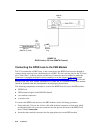
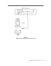
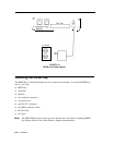

To connect the RPSD Lock device to the administration terminal or printer, use the
following procedure:
1
Using Table 2-1, make up a DB25 connector with EIA-RS232 cable for the Aux. Port
of the RPSD Lock.
2
Make up the appropriate connector for the terminal or printer according to the pin
descriptions in Table 2-1.
3
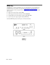
Connect the first DB25 connector to the Aux. Port on the back of the RPSD Lock.
4
Connect the other end of the cable you just made up to the terminal or printer, as appropriate.
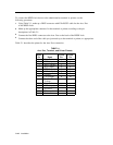
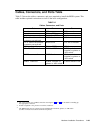
Table 2-1 describes the pinout for the Aux. Port connection.
TABLE 2-1
Aux. Port, Terminal, and Printer Pinouts
2-16
Installation
RPSD
To DTE To DCE
Pin
Signal
Pin
Pin
1 Not used
2 TXD (input)
2
3
3 RXD (output)
3
2
4 RTS (input)
4 6
5
CTS (output)
5
5
6
DSR (output)
6
4
7 Ground
7
7
8 CD (output)
8
20
9
Positive Test
Voltage
10-19 Not used
20 DTR (input)
20 8
21 Not used
22 RI (output)
22
22
23-25 Not used