


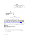

Modular
Plug
RJ11
Jack
CO Line
(RMATS Channel)
Modular
Plug
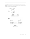
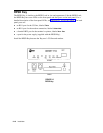
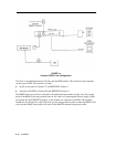
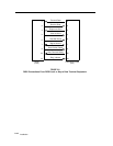
FIGURE 2-5
RPSD Lock to CO Line (RMATS Channel)
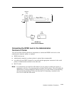
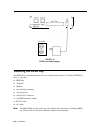
Connecting the RPSD Lock to the PBX Modem
The 212A modem has a DB25 input, so the connection to the RPSD Lock must be adapted to
connect the tip and ring from a modular plug to a DB25. The two relevant pins for the 212A are
pins 7 and 8. Pin 7 is the tip and pin 8 is the ring. Connectors must be adapted to make this
connection. A detailed description of this connection is in this chapter in the section titled
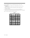
Connecting the RPSD Lock to the Administration Terminal or Printer. Table 2-1 provides the
pinout for the Aux. Port. Further information, for either the 212A modem or any other modem,
should be obtained from the documentation accompanying that modem.
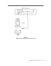
The following components are needed to connect the RPSD Lock device to the PBX modem:
■
RPSD Lock
■
PBX modem assigned to the RMATS channel
■ two modular connectors
■
6 position wire
To connect the RPSD Lock device to the PBX modem, use the following procedure:
1
Using either the 7-foot or the 14-foot cable with modular connectors on both ends which
accompanied the Lock, insert one connector into the port on the back of the RPSD Lock
device labeled
Subscriber.
2
Insert the other modular connector into the appropriate port on the PBX modem.
2-14
Installation