


4
Installation: ATTO iPBridge 2500R/D
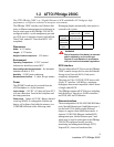
Serial interface
The RS-232 serial port provides support for
remote monitoring and management through a
command line interface. It is set at the factory at
115,200 bps.
Pin outs of the RJ11 connector, part number CBL-
0911-001 are
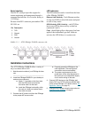
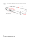
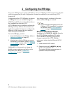
LED indicators
The LED indicators can be viewed from the front
of the iPBridge 2500R/D.
Ethernet Link & Activity:
Each Ethernet port has
its own set of LEDs to show link status and speed
as well as busy status.
SCSI 0 Activity, SCSI 1 Activity:
each SCSI bus
has its own LED to show activity on that bus
(numbered 0 and 1).
Fault:
should light yellow when power has been
applied, then immediately go dark. Software
activates the LED if there is a system error.
Exhibit 1.1-1 ATTO iPBridge 2500R/D connector side
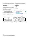
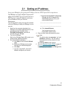
Installation instructions
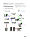
The ATTO iPBridge 2500R/D offers a variety of
ways to connect into a SAN.
1 Note the serial number of your iPBridge for later
use:
_____________________________________
2 Install the iPBridge 2500R/D in your desktop or
rackmount environment.
a. Attach “L” brackets so that front side
with the LEDs face front and the
connector side is at the back.
b. Install the iPBridge horizontally within
the rack so it does not reduce the air
flow within the rack.
3 Connect the AC power cord from the iPBridge
to the proper AC source outlet.
a. Properly ground the iPBridge to the
rack equipment. The earth ground
connection must be maintained.
b. The power requirements plus the
power draw of the other equipment in
the rack must not overload the supply
circuit and/or wiring of the rack.
4 Connect SCSI devices to the iPBridge. and
attach CAT 6 or CAT 5E cables to the GbE data
port(s) on the iPBridge. (For details, refer to the
Appendix, Cabling, on page iii).
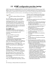
5 Configure the iPBridge using the instructions in
Configuring the iPBridge
on page 9.
Pin Description
2TXD
3Ground
4RXD
5Ground