


7
ATTO Technology Inc. iPBridge Installation and Operation Manual
GbE cables must be at least CAT-5E certified for
1000 Mb/sec. use.
Serial interface
The RS-232 serial port provides support for
remote monitoring and management through a
command line interface. It is set at the factory at
115,200 bps.
Pin outs of the RJ11 connector, part number CBL-
0911-001 are
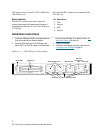
Installation instructions
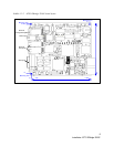
1 Install the iPBridge 2500C in the target device.
(See the board layout diagram below)
2 Connect SCSI devices to the iPBridge. and
attach CAT 6 or CAT 5E cables to the GbE data
port(s) on the iPBridge. (For details, refer to the
Appendix, Cabling, on page iii).
3 Connect to power.
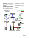
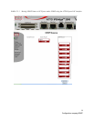
4 Configure the iPBridge using the instructions in
Configuring the iPBridge
on page 9.
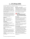
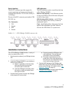
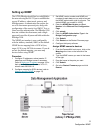
Exhibit 1.2-1 ATTO iPBridge 2500C faceplate
Pin Description
2TXD
3 Ground
4RXD
5 Ground
SCSI ports
Ethernet data ports RS-232 port
Ethernet
management
port
Fault LED
SCSI LEDs
Ethernet port link and activity LEDs
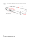
SCSI Port 0
SCSI Port 1
Fault
Management Port
RS-232
Data Port 0 Data Port 1