


12 DSR Installer/User Guide
Verification of Ethernet/computer connections
DSR appliance
The front panel of the DSR features two LEDs describing the Ethernet
connection. The top green LED is the Link indicator. It will illuminate when a
valid connection to the network is established and blink when there is activity
on the port. The lower amber LED, labeled 100M, will indicate that you are
communicating at the 100 Mb rate.
Additionally, there are two LEDs above each port number on the front of your
appliance: one green and one amber. The green LED will illuminate when the
attached system is powered. The amber LED will illuminate when that port is
selected by the DSView Client.
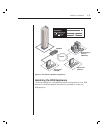
DSRIQ modules
PS/2, Sun and USB DSRIQ modules are available for attaching computers to
your DSR appliance.
The DSRIQ-SRL serial module is used to connect serial devices to your DSR
appliance and features two green LEDs: a POWER LED and a STATUS LED.
The POWER LED indicates that the attached computer is powered. The
STATUS LED indicates that a valid UTP connection has been made to a DSR
appliance. The DSRIQ-SRL prevents a serial break from the attached device if
the module loses power. However, a user can generate a serial break with the
attached device by pressing Alt-B in the Terminal Applications menu.
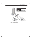
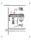
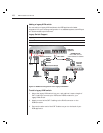
Setting up your network
The DSR system uses IP addresses to uniquely identify the server running
DSAuth, the DSR appliances and the computers running DSView. The DSR
supports both BootP (a subset of DHCP) and static IP addressing. Avocent
recommends that IP addresses be reserved for each appliance and that they
remain static while the DSR appliances are connected to the network. For
additional information on how the DSR uses the TCP protocol, see Appendix B
of the DSView Installer/User Guide. Figure 2.1 shows the DSR in a
network configuration.