


1-16 (No.PA019)
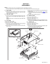
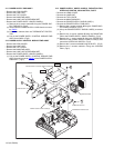
3.11 POWER SUPPLY PWB ASS'Y
• Remove the LENS COVER.
• Remove the LAMP UNIT.
• Remove the TOP COVER.
• Remove the MAIN PWB ASS'Y.
• Remove the LAMP UNIT UPPER BRACKET.
• Remove the POWER SUPPLY SHIELD CASE(1).
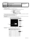
(1) Remove the 4 screws marked P fixing the POWER SUP-
PLY PWB ASS'Y. (Fig.5)
(2) Disconnect the POWER SUPPLY CORD from the connec-
tor CN001
.
(3) Pull out the harness from the THERMOSTAT PROTEC-
TOR.
(4) Pull out the POWER SUPPLY CONTROL MODULE PWB
ASS'Y from CN005. (Fig.5)
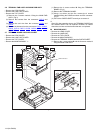
3.12 POWER SUPPLY CONTROL MODULE PWB ASS'Y
• Remove the LENS COVER.
• Remove the LAMP UNIT.
• Remove the TOP COVER.
• Remove the MAIN PWB ASS'Y.
• Remove the LAMP UNIT UPPER BRACKET.
• Remove the POWER SUPPLY SHIELD CASE(1).
(1) Pull out the POWER SUPPLY CONTROL MODULE PWB
ASS'Y from the connector CN005
of the POWER SUPPLY
PWB ASS'Y. (Fig.5)
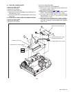
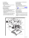
3.13 POWER SUPPLY SHIELD CASE(2), RADIATION FAN,
INTERLOCK SWITCH, COOLING FAN1, DUCT1
• Remove the LENS COVER.
• Remove the LAMP UNIT.
• Remove the TOP COVER.
• Remove the MAIN PWB ASS'Y.
• Remove the POWER SUPPLY SHIELD CASE(1).
• Remove the POWER SUPPLY PWB ASS'Y.
(1) Remove the 4 screws marked Q fixing the POWER SUP-
PLY SHIELD CASE(2). (Fig.5)
(2) Lift up the POWER SUPPLY SHIELD CASE(2) to remove
it.
(3) Remove the 2 screws marked R fixing the RADIATION
FAN to the POWER SUPPLY SHIELD CASE(2). (Fig.5)
(4) Remove the 1 screw marked S fixing the INTERLOCK
SWITCH to the POWER SUPPLY SHIELD CASE(2), and
remove the INTERLOCK SWITCH. (Fig.5)
(5) Remove the 2 screws marked b fixing the DUCT1. (Fig.5)
(6) Remove the 2 screws marked c fixing the COOLING
FAN1. (Fig.5)
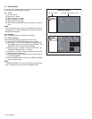
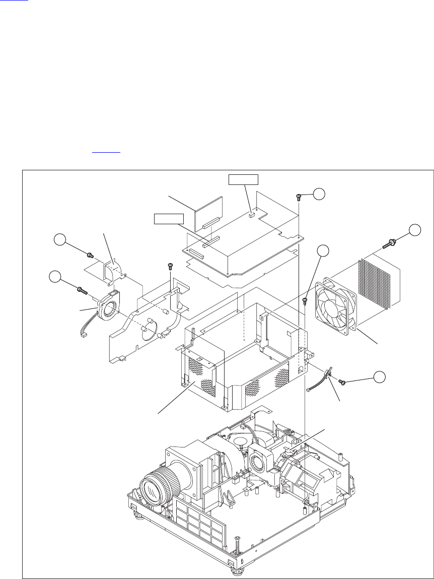
Fig.5
RADIATION FAN
P
(x4)
CN001
R
(x2)
Q
(x4)
S
(x1)
b
(x2)
c
(x2)
CN005
INTERLOCK SWITCH
THERMOSTAT PROTECTOR
POWER SUPPLY SHIELD CASE(2)
COOLING FAN1
DUCT1
POWER SUPPLY CONTROL MODULE PWB ASS'Y