


1-4 (No.PA019)
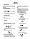
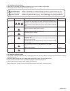
1.1.2 Safety Check after Servicing
Examine the area surrounding the repaired location for damage
or deterioration. Observe that screws, parts and wires have been
returned to original positions, Afterwards, perform the following
tests and confirm the specified values in order to verify compli-
ance with safety standards.
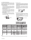
(1) Insulation resistance test
Confirm the specified insulation resistance or greater be-
tween power cord plug prongs and externally exposed
parts of the set (RF terminals, antenna terminals, video and
audio input and output terminals, microphone jacks, ear-
phone jacks, etc.).See table 1 below.
(2) Dielectric strength test
Confirm specified dielectric strength or greater between
power cord plug prongs and exposed accessible parts of
the set (RF terminals, antenna terminals, video and audio
input and output terminals, microphone jacks, earphone
jacks, etc.). See Fig.1-1-11 below.
(3) Clearance distance
When replacing primary circuit components, confirm spec-
ified clearance distance (d), (d') between soldered termi-
nals, and between terminals and surrounding metallic
parts. See Fig.1-1-11 below.
Fig.1-1-8
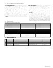
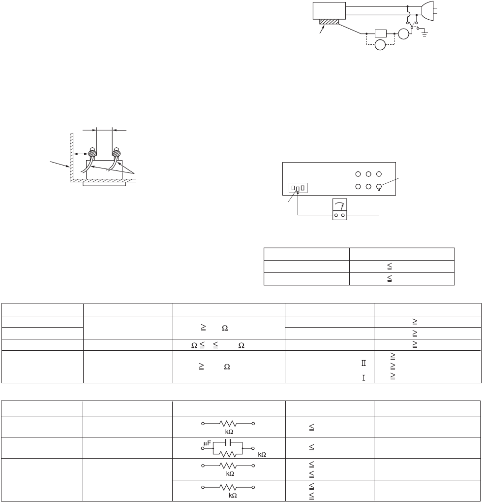
(4) Leakage current test
Confirm specified or lower leakage current between earth
ground/power cord plug prongs and externally exposed ac-
cessible parts (RF terminals, antenna terminals, video and
audio input and output terminals, microphone jacks, ear-
phone jacks, etc.).
Measuring Method : (Power ON)Insert load Z between
earth ground/power cord plug prongs and externally ex-
posed accessible parts. Use an AC voltmeter to measure
across both terminals of load Z. See Fig.1-1-9 and follow-
ing Fig.1-1-12.
Fig.1-1-9
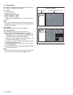
(5) Grounding (Class 1 model only)
Confirm specified or lower grounding impedance between
earth pin in AC inlet and externally exposed accessible
parts (Video in, Video out, Audio in, Audio out or Fixing
screw etc.).Measuring Method:
Connect milli ohm meter between earth pin in AC inlet and
exposed accessible parts. See Fig.1-1-10 and grounding
specifications.
Fig.1-1-10
Fig.1-1-11
Fig.1-1-12
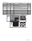
NOTE :
These tables are unofficial and for reference only. Be sure to confirm the precise values for your particular country and locality.
Chassis
Power cord
primary wire
d'
d
ab
c
V
A
Externally
exposed
accessible part
Z
Exposed accessible part
Grounding Specifications
AC inlet
Region
USA & Canada
Europe & Australia
Grounding Impedance
(
Z
)
Z 0.1 ohm
Z 0.5 ohm
Earth pin
MIlli ohm meter
AC Line Voltage
Region
Japan
Europe & Australia
R 1 M /500 V DC
USA & Canada
1 M R 12 M /500 V DC
R 10 M /500 V DC
Insulation Resistance
(
R
)
Dielectric Strength
Clearance Distance
(
d
)
,
(
d'
)
100 V
100 to 240 V
110 to 130 V
110 to 130 V
200 to 240 V
AC 1 kV 1 minute
AC 1.5 kV 1 minute
AC 1 kV 1 minute
(
Class
)
(
Class
)
AC 3 kV 1 minute
AC 1.5 kV 1 minute
d, d' 3 mm
d, d' 4 mm
d, d' 3.2 mm
d' 8 m m
(
Power cord
)
d' 6 m m
(
Primary wire
)
d 4 mm
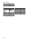
AC Line Voltage
Region
Japan
Europe & Australia
USA & Canada
Load Z
Leakage Current (i)
a, b, c
100 V
110 to 130 V
110 to 130 V
220 to 240 V
i 1 mA rms
i 0.5 mA rms
i 0.7 mA peak
i 2 mA dc
i 0.7 mA peak
i 2 mA dc
Exposed accessible parts
Exposed accessible parts
Antenna earth terminals
Other terminals
1
1.5
2
50
0.15