


1716
INSTALLATIONINSTALLATION
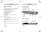
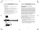
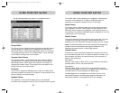
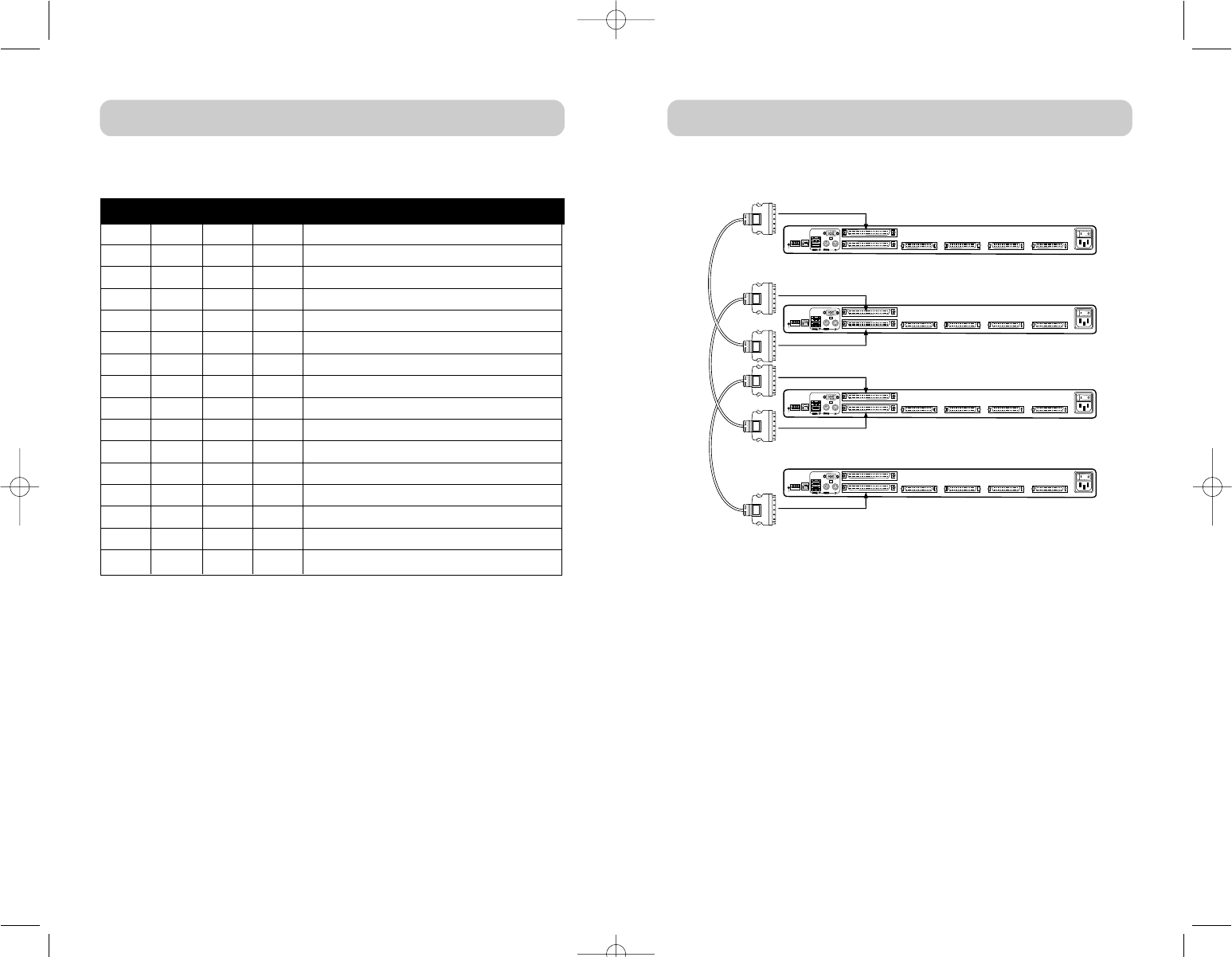
Example: Four KVM Switches (F1DE108B) are daisy-chained together to
control 32 computers. The DIP Switch on the Primary Switch is set to
“BANK address 00” and the Secondary Switches are each set to a unique
BANK (between 01 and 15).
Installation
Before you begin:
1. Make sure that all computers and KVM Switches are powered off and
that each KVM Switch has been assigned a unique BANK address.
2. Place all Primary and Secondary Switches in the desired location.
3. Connect the servers to the KVM Switch as previously described for a
standalone configuration.
4. Connect the Console monitor, keyboard, and mouse to the Console
ports of the Primary KVM Switch(es), as previously described for
standalone configuration, skipping steps 5 and 6.
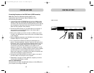
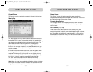
Connecting the Daisy-Chain Cable
5. Using the Daisy-Chain Cable (F1D9402-XX), connect one end to the
“Daisy-Chain OUT” port on the first KVM Switch.
6. Connect the other end of the Daisy-Chain Cable to the “Daisy-Chain
In” port of the second KVM Switch.
Note: It does not matter which unit is the Primary Switch, only that the
cables are always connected “OUT to IN” or “IN to OUT”.
Adding Additional Units
7. Continuing in the same manner, using the Daisy-Chain Cable
(F1D9402-XX), connect “Daisy-Chain IN” to “Daisy-Chain OUT” on
all subsequent units.
*** Cautions and Warnings ***
Never connect “Daisy-Chain IN” to “Daisy-Chain IN” or “Daisy-Chain
OUT” to “Daisy-Chain OUT”. This may produce unpredictable results
and may cause damage to the KVM Switch.
console
USB
flash
bank
select
reset
PS/2
daisy chain OUT
daisy chain IN
CPU 01/02 CPU 03/04 CPU 05/06 CPU 07/08
90-264 VAC. 47-63 Hz
1 2 3 4
console
USB
flash
bank
select
reset
PS/2
daisy chain OUT
daisy chain IN
CPU 01/02 CPU 03/04 CPU 05/06 CPU 07/08
90-264 VAC. 47-63 Hz
1 2 3 4
console
USB
flash
bank
select
reset
PS/2
daisy chain OUT
daisy chain IN
CPU 01/02 CPU 03/04 CPU 05/06 CPU 07/08
90-264 VAC. 47-63 Hz
1 2 3 4
console
USB
flash
bank
select
reset
PS/2
daisy chain OUT
daisy chain IN
CPU 01/02 CPU 03/04 CPU 05/06 CPU 07/08
90-264 VAC. 47-63 Hz
1 2 3 4
Example of Daisy-Chain Configuration:
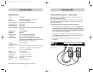
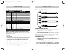
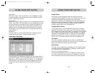
DIP SWITCH CONFIGURATION CHART
DIP SWITCH# BANK ADDRESS
DOWN DOWN DOWN DOWN BANK 00 PRIMARY / SECONDARY (Default)
UP DOWN DOWN DOWN BANK 01 PRIMARY / SECONDARY
DOWN UP DOWN DOWN BANK 02 PRIMARY / SECONDARY
UP UP DOWN DOWN BANK 03 PRIMARY / SECONDARY
DOWN DOWN UP DOWN BANK 04 SECONDARY
UP DOWN UP DOWN BANK 05 SECONDARY
DOWN UP UP DOWN BANK 06 SECONDARY
UP UP UP DOWN BANK 07 SECONDARY
DOWN DOWN DOWN UP BANK 08 SECONDARY
UP DOWN DOWN UP BANK 09 SECONDARY
DOWN UP DOWN UP BANK 10 SECONDARY
UP UP DOWN UP BANK 11 SECONDARY
DOWN DOWN UP UP BANK 12 SECONDARY
UP DOWN UP UP BANK 13 SECONDARY
DOWN UP UP UP BANK 14 SECONDARY
UP UP UP UP BANK 15 SECONDARY
P74042_F1DE108E_man.qxd 5/6/02 10:06 AM Page 16