98
INSTALLATION
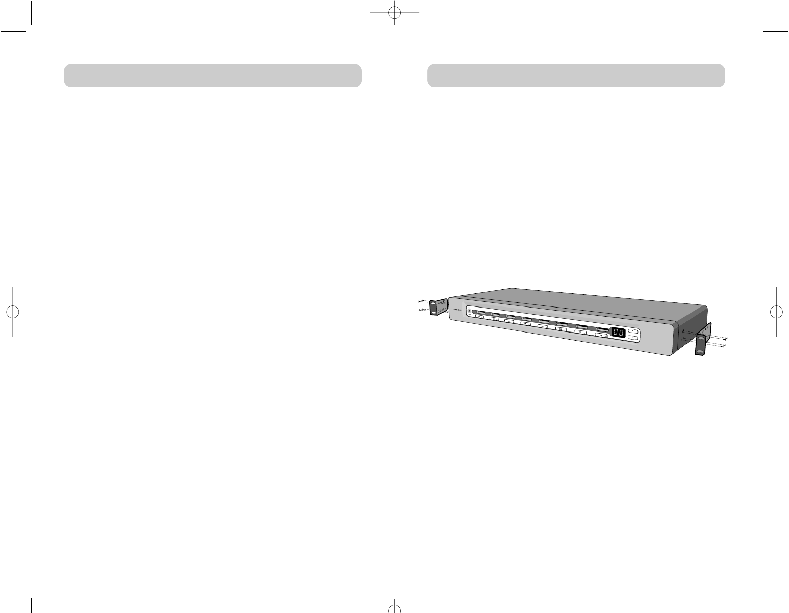
3. Attach the bracket to the side of your KVM Switch with the Phillips
screws provided. (See Fig. 1)
4. Mount the KVM Switch to the rack rail assembly.
Note: If this KVM Switch will be daisy-chained to another Switch, set the
BANK address prior to installing on a rack. Refer to the section in this
User Manual labeled “Multiple KVM Switch—Installation
(Daisy-Chaining)”.
*** Cautions and Warnings ***
Before attempting to connect anything to the KVM Switch or your
server(s), please ensure that all KVM Switches and servers are
powered off. Belkin Components is not responsible for damage
caused by these actions.
INSTALLATION
PRE-CONFIGURATION
The enclosure of the KVM Switch is designed for standalone or
rack-mount configuration. The 8-Port KVM Switches are natively
rack-mountable in standard 19-inch server racks. Rack-mount hardware
is included with these Switches for a sturdy rack installation.
Consider the following when deciding where to place the KVM Switch:
• Whether or not you intend to use the direct-access port selectors;
• The lengths of the cables attached to your keyboard, monitor,
and mouse;
• The location of your computers in relation to your console; and
• The lengths of the cables you use to connect your computers to the
KVM Switch.
Cable Distance Recommendations
For PS/2 computers
We recommend that PS/2 cable length be limited to 25 feet for best
video performance. Beyond that length, the probability of video
degradation increases.
For USB computers
We recommend that USB cable length be limited to 12 feet for best
performance. Beyond 12 feet, the probability of signal failure is likely, and
this may cause the device to fail.
Installing the KVM Switch into a Server Rack
OmniView ENTERPRISE Series 8-Port KVM Switches include adjustable
mounting brackets ideal for installation in 19-inch racks. The mounting
brackets feature three adjustable positions that allow the front panel to
mount flush to your rack-mounted servers and rack rails, or extended past
the front of the rails.
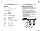
1. Remove the adjustable brackets from the box.
2. Determine how far you would like the KVM Switch to protrude from
the rack and select a bracket-hole scheme.
Fig. 1
P74042_F1DE108E_man.qxd 5/6/02 10:06 AM Page 8


