


Rev. 2.01
- 25 -
SRP-350/352plusA&C
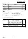
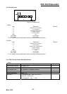
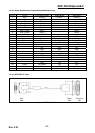
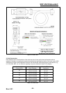
3-5-1(c) Cable Connection
Figure 3-7 RS-232C Cable Connection
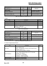
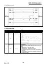
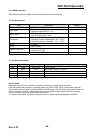
3-5-1(d) Signal Description
Pin No. Signal Name Signal Direction Function
BODY Frame GND - Frame Ground
2 TXD Output Transmit Data
3 RXD Input Receive Data
6 DSR Input
This signal indicates whether the host computer can receive
data. (H/W flow control)
1) MARK(Logic1) : The host can receive a data.
2) SPACE(Logic0) : The host can not receive a data.
3) The printer transmits a data to the host, after confirming
this signal.
4) When XON/XOFF flow control is selected, the printer
does
not check this signal.
7 Signal GND - Signal Ground
20 DTR Output
This signal indicates whether the printer is busy. (H/W flow
control)
1) MARK(Logic1) : The printer is busy.
2) SPACE(Logic0) : The printer is not busy.
3) The host transmits a data to the printer, after confirming
this signal.
4) When XON/XOFF flow control is selected, the host does
not check this signal.
Table 3-15 RS-232C Pin Description
Printer
Side(25P)
Host
Side(25P)
(S.G) 1
(TXD) 2
(RXD) 3
(DSR) 6
(DTR) 20
(S.G) 7
1 (S.G)
2 (TXD)
3 (RXD)
6 (DSR)
20 (DTR)
7 (S.G)