


Rev. 2.01
- 34 -
SRP-350/352plusA&C
4-3 Special Circuit Descriptions
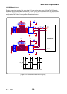
4-3-1 Power Circuit
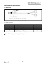
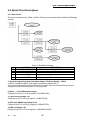
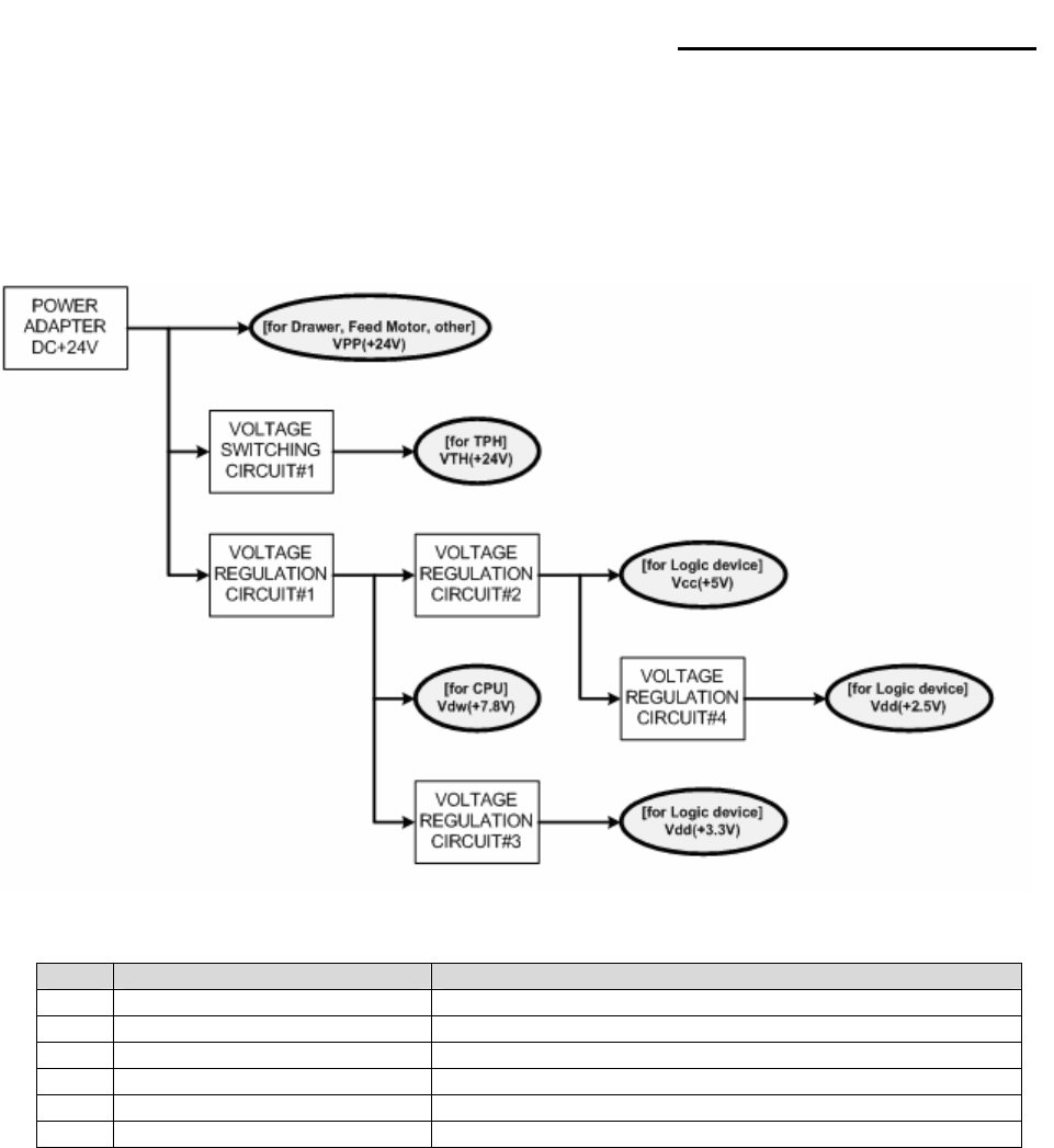
This system is operated under 100Vac or 240Vac. The power circuit supplies the three differential DC voltage
sources.
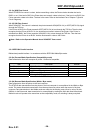
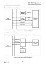
[Figure 4-3 Power Block Diagram]
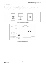
1) Drawer Driving and Feed, Auto Cutter Motor Voltage, TPH Driving Voltage : +24VDC
+24VDC is supplied from SMPS. This Voltage is smoothed by capacitors (CL1).
This voltage is used as a Cash Drawer Solenoid Driving voltage, Step motor driving voltage and a source
voltage of the other voltage sources and TPH Driving Voltage.
2) Voltage : +7.8V (CPU Download Voltage)
Change the input 24V to 7.8V by a regulation. U1(LM2575S-ADJ)
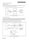
3) Logic IC Driving Voltage: +5V
Change the input 7.8V to 5V by a regulation. U2(BA17805-E2)
4) CPU, Flesh, SRAM, Reset Voltage: +3.3V
Change the input 7.8V to 3.3V by a regulation. U3(BA033FP-E2)
5) USB core Voltage: +2.5V
Change the input 5V to 2.5V by a regulation. U202(BH25FB1WHFV)
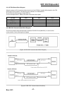
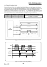
No. VOLTAGE DESCRIPTION
1 VPP(+24VDC) Cash Drawer Solenoid Driving / Step Motor Voltage
2 VTH(+24VDC) Thermal Printer Head (TPH) Voltage
3 Vdw(+7.8VDC) CPU Download Voltage
4 Vcc(+5VDC) Logic, Sensor Voltage
5 Vdd(+3.3VDC) CPU, Flesh, SRAM, Reset Voltage
6 Vdd(+2.5VDC) USB core Voltage