


724-746-5500 | blackbox.com
Page 100
724-746-5500 | blackbox.com
Chapter 4: E2 Controller
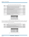
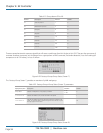
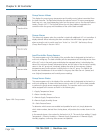
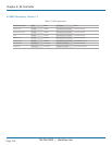
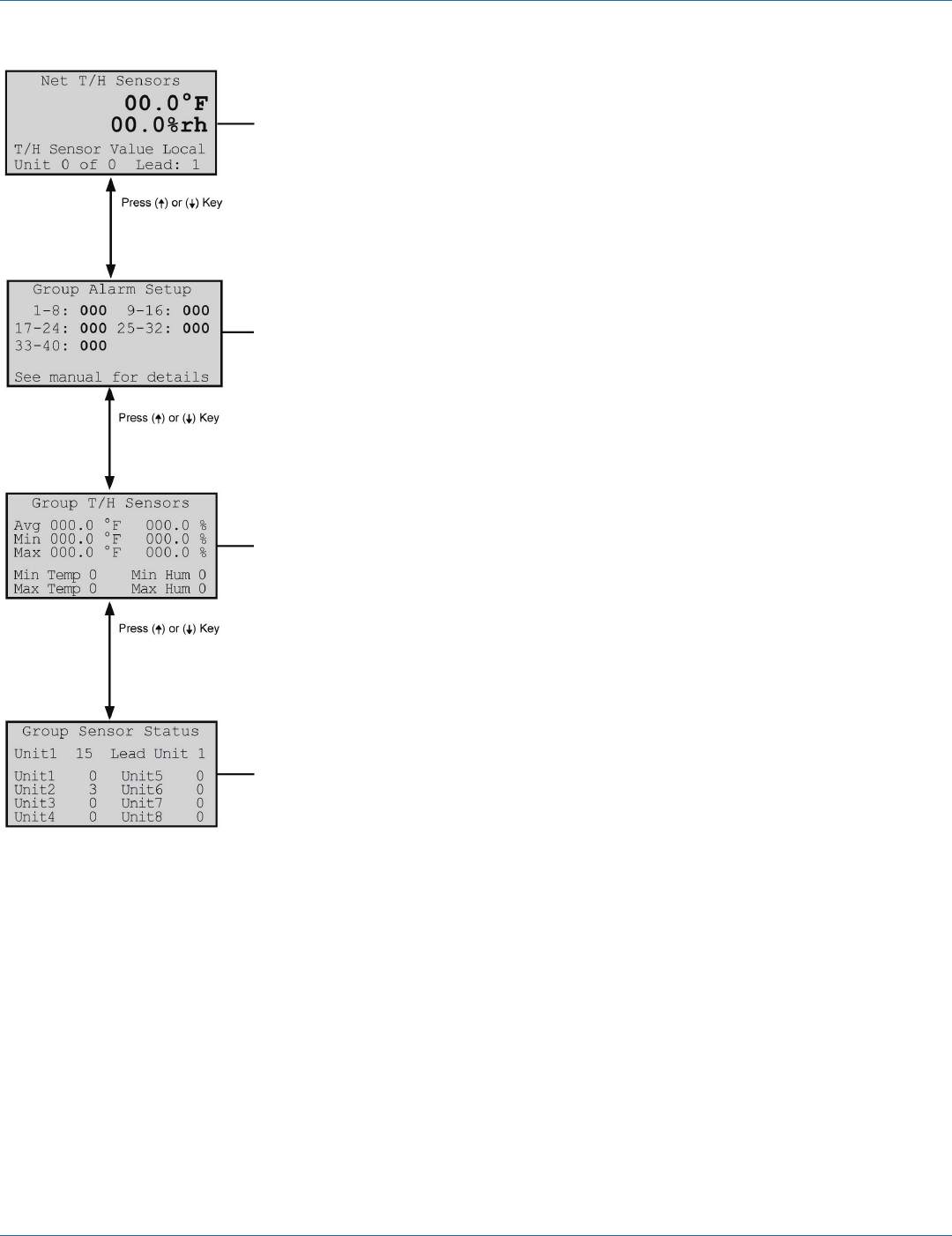
Group Sensor Values
This displays the current group temperature and humidity control values transmitted from
the Lead controller. The field below displays the selected control T/H sensor arrangement
(lead, avg, min, max, local) depending upon how the group is set up. See Service>Options
screens, Section 4.6.2.7. The last field shows the unit group address assigned to the
controller within the group and the address of the current lead controller.
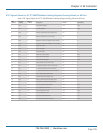
Group Alarms
This screen only appears when the controller is wired with additional A/C unit controllers. It
displays bitmask values indicating the alarm conditions that will initiate a group internal
alarm causing the unit to switch over from “Active" to "Unit Off.” See Factory>Group
(Group Alarm Setup) in Section 4.6.2.6.
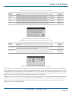
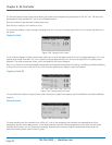
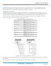
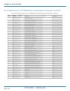
Lead Controller Group Sensors
This screen appears only in the display of the controller that is designated as the lead in a
multi-unit workgroup. The lead controller polls the temperature and humidity sensors from
all the A/C units in the work group and displays the averaged values. It also displays the
value of the minimum (lowest) temperature sensor and the value of the minimum humidity
sensor in the A/C group and, conversely, displays the value of the maximum (highest)
temperature sensor and maximum humidity sensor in the A/C group. The fields at the
bottom are the addresses of the controllers in the group that have the min. (lowest) and
max. (highest) temperature and humidity sensor readings.
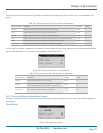
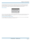
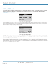
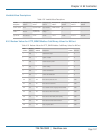
Group Sensor Status
This screen appears only in the display of the controller that is designated as the Lead in a
multi-unit workgroup. It shows what sensors exist on each A/C unit for the lead controller
to perform the group sensor averaging calculation. The numbers are the sums of index
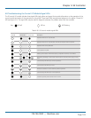
values assigned to the sensors as shown in the following key:
1 = Supply Temperature Sensor
2 = Return Humidity Sensor
4 = Remote Supply Temperature Sensor
8 = Remote Supply Humidity Sensor
16 = Static Pressure Sensor
To determine which sensors are enabled and operable for each unit, simply determine
which index numbers, derived from the key above, will produce the number shown in the
screen.
In the example shown, the number for the lead unit is 15. This results from adding 1 Supply
Temperature + 2 Return Humidity + 4 Remote Supply Temperature + 8 Remote Supply
Humidity together, confirming those sensors are operable.
Figure 4-90. Group screens.