


724-746-5500 | blackbox.com
Page 34
724-746-5500 | blackbox.com
Chapter 2: Installation
CAUTION
Before operating the unit, you must connect an adequate unit-to-ground to the unit.
2.9.1.1 Single-Phase Units 208/230 V
The supply voltage for units that are designed for 208-V operation must have a tolerance within -5% and +10%. If the measured
supply voltage is 230 V, the unit can operate with a tolerance of ±5% if the following change is made. The control transformers
within the system must have the primary wire connected to its respective 240V tap instead of the 208V tap.
2.9.1.2 Three-Phase Units
Three-phase units are designed to have the L1, L2, and L3 supply wires connected to corresponding L1, L2, and L3 line terminals
of the non-fused service switch. The unit will operate correctly if the supply wires are connected in this manner.
CAUTION
Improper wire connections will result in the reverse rotation of the fans/blower motors and compressor and may eventually result
in damage to the compressor. To correct this problem, exchange any two of the incoming main power wires at the main power
service disconnect switch. Do NOT rewire the unit’s individual components.
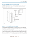
2.9.2 Optional Equipment
Additional control wires may be required depending on the options that were purchased with your unit. Optional sensors are to
be connected directly to the control terminal board in the Cold Row electric box. You may route the wires through the top or
bottom of the cabinet as preferred using the available knock-outs. Refer to the electrical drawing supplied with your unit to
determine the total number of interconnecting conductors required for your system.
NOTE: All wiring must be provided in accordance with local and National Electrical Code requirements for Class 2 circuits.
NOTE: The control transformer(s) supplied with the equipment have been sized and selected based upon the expected loads for
each system.
CAUTION
Do not connect any additional loads to the system control transformers. Connecting additional loads to the factory-supplied
control transformer(s) may result in overloading of the transformer(s).
2.9.2.1 Remote Water Detector
Refer to Section 2.6.1. Each remote water detector used will require two conductors to be wired to the control terminal block
within the unit electrical box. The wire insulation must be rated at 600 V.
2.9.2.2 Remote Temperature/Humidity Sensor
Refer to Section 2.6.2. The remote temperature/humidity sensor is equipped with a shielded cable. The shield is to be terminated
at the unit electric box. The electric box includes a control terminal block with box-type lugs for wire connections.
2.9.2.3 Remote On/Off
The unit can remotely turn off the air-conditioning system. A normally closed switch is required for this purpose (customer
furnished). Connect two conductors from the normally closed switch to the control terminal block located within the unit electric
box. Refer to the supplied electrical schematic for the specific power rating of the switch and for wiring details.
See Section 4.4.5 for additional information on the remote on/off feature.
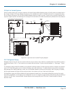
2.9.3 Outdoor Equipment
The following sections detail field power wiring required for a typical system. Additional conductors may be required depending
on the options purchased with the equipment. Refer to the electrical drawing supplied with your unit for the appropriate field
wiring terminations required specifically for your system.
2.9.3.1 Water-Cooled Systems (CRDX-W-FS-12KW, CRDX-W-FS-24KW Models)
Systems equipped with an internal water-cooled condenser do not require field wiring to external components other than to
optional sensors as selected (e.g. Flow Sensors, Remote Supply Air T/H sensor, Air Pressure, Customer Alarm Inputs).