


724-746-5500 | blackbox.com
724-746-5500 | blackbox.com
Page 93
Chapter 4: E2 Controller
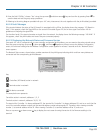
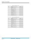
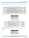
Table 4-15. Factory>Group>Capacity Assist (Screen 4) parameters.
Display
Description Description Variables Default
Humid Cut in Enter relative humidity setpoint offset for humidifying capacity assist operation to begin. -99.9 to 99.9 -4.0
Cut out Enter relative humidity setpoint offset for humidifying capacity assist operation to stop. -99.9 to 99.9 0.0
Dehum Cut in Enter relative humidity setpoint offset for dehumidifying capacity assist operation to begin. -99.9 to 99.9 4.0
Cut out Enter relative humidity setpoint offset for dehumidifying capacity assist operation to stop. -99.9 to 99.9 0.0
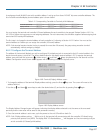
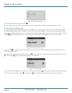
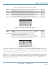
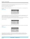
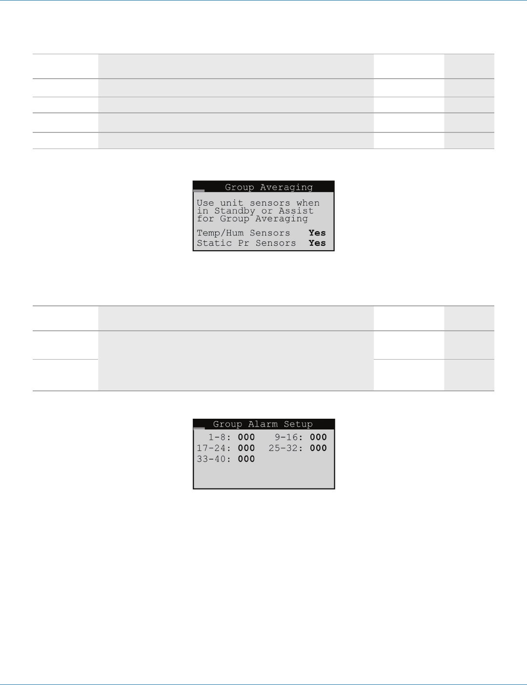
Figure 4-80. Factory>Group>Group Averaging (Screen 5).
Table 4-16. Factory>Group>Group Averaging (Screen 5) parameters.
Display
Description Description Variables Default
Temp/Hum Sensors
Enter Yes for the unit to respond to its local sensors to enable Standby or Capacity Assist
operation. Enter No for unit to respond to the Group sensors.
0 = No
1= Yes
Yes
Static Pr Sensor
0 = No
1= Yes
Yes
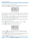
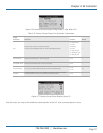
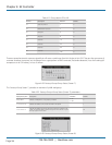
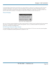
Figure 4-81. Factory>Group>Group Alarm Setup (Screen 6).
This screen may be accessed on the controller for each unit to be grouped. You may enter bitmask numbers to establish which
alarm conditions for that particular unit will initiate a group internal alarm. The group alarms may be set before the A/C units are
wired together. When a group alarm condition is detected by a unit, it causes that unit to temporarily switch over from “Active”
to “Off” and if another unit is available in the group, it may rotate into its place. A status massage “Off by internal alarm” will
appear in the Main screen of the unit that detected the group alarm and switched off.
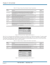
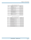
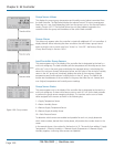
See Section 4.5.5.5 for an overview of how to select alarms using bitmask values. The Group Alarms bitmask values are shown in
the Tables 4-17–4-21. The settings may be viewed at the Info level following the network sensors screen. If an alarm condition
appearing in the following tables is detected, it needs to be reset at the unit's display terminal or via the BMS for the unit to
return to “Active” and resume operation.