


724-746-5500 | blackbox.com
Page 78
724-746-5500 | blackbox.com
Chapter 4: E2 Controller
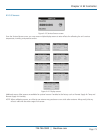
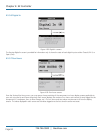
NOTE: Display screens shown with a dashed border appear only if the application feature is enabled.
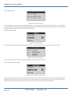
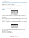
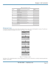
Custom Alarm Setup (Optional)
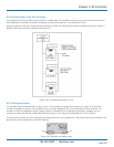
The E2 controller may be enabled to activate a Custom Alarm output and energize a designated N.O./N.C. relay. A custom alarm
output is set up by adding the binary bitmask numbers assigned to the specific alarms and signal failures you wish to monitor via
the relay and then entering them in the Custom Alarm Setup screen.
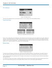
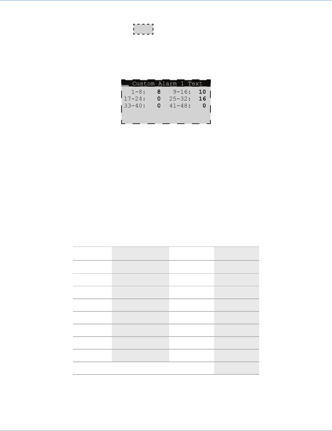
Figure 4-56. Custom Alarm Setup screen.
NOTE: Custom alarm display screens may appear even if the feature is not enabled. In this case, changes made to these screens
will have no effect.
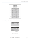
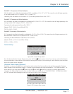
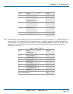
You can select any mix of the 48 alarm variables as shown in the tables that follow. As an example, for a custom alarm based
only on the occurrence of moisture alarm, fire/smoke, condensate pan, failure of the return humidity sensor, you would enter the
following bitmask values for the applicable alarm numbers and enter 0 for the rest:
Custom Alarm number 1–8...............Moisture alarm (No. 4) = 8
Custom Alarm number 9–16.............Fire/smoke (No. 10) + Condensate pan (No. 12) = 10 (2+8)
Custom Alarm number 25–32............Return humidity sensor (No. 29) = 16
The custom alarms are set up by entering the bitmask totals developed from the tables shown next.
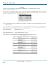
Table 4-4. Alarms 1 to 8.
Number Description Bitmask Default
1 Upper fan alarm
1 1
2 Lower fan alarm
2 2
3 Middle fan alarm
4 4
4 Moisture alarm
8 8
5 Emergency shutdown
16 16
6 Remote shutdown
32 32
7 Customer alarm
64 0
8 Airflow alarm
128 128
Factory Default Bitmask Total
191