


724-746-5500 | blackbox.com
Page 26
724-746-5500 | blackbox.com
Chapter 2: Installation
Piping Connections
CAUTION
The cooling coil (and associated piping circuits) are pressurized (up to 100 psi) and sealed when they leave the factory. Before
installing the interconnecting piping, release the pressure via an available stem valve or Schrader valve prior to uncapping the
pipes.
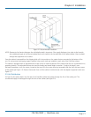
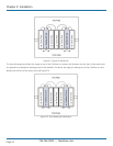
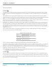
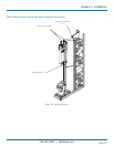
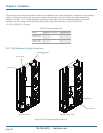
Fluid supply and return lines are routed to either the top or bottom of the cabinet as specified when the Cold Row system is
ordered (see Figures 2-8 and 2-9). On units that are piped from the top, the supply and return connections are made outside the
cabinet. On units that are piped from the bottom, the supply and return connections are made inside the cabinet.
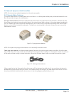
Pipe connections are threaded NPT connections. The pipes are labeled; i.e. “Supply,” “Return.” When making the connections, a
Teflon
®
tape thread sealant is recommended to minimize internal fouling of the piping.
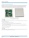
Field piping is not necessarily the same size as the unit’s pipe connections. Piping should be sized to match the system pressure
drop and flow capacity, and may require reducing fittings to match the connection size on the air conditioner. An air vent and
several Schrader valves are installed in the precision A/C unit piping. We recommend providing manual shut-off valves for both
the supply and return fluid for isolating the unit when performing routine maintenance or repairs. Refer to the piping diagram
supplied with your unit.
NOTE: Install a 60-mesh strainer in the supply pipe. Make sure the strainer is readily accessible for servicing or replacement.
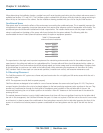
For pipe connection sizes, refer to the following table:
Table 2-3. Pipe connection sizes.
Model # Water Glycol Inlet/Outlet Condensate Drain
CRDX-G-FS-12W,
CRDX-G-FS-24W
1
1
⁄4"
1
⁄2
"
CRDX-W-FS-12W,
CRDX-W-FS-24W
1
1
⁄4"
1
⁄2
"
NOTE: Use standard refrigeration practices for piping, leak testing, and filling the water glycol circuit.
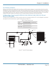
Use vibration isolating supports to isolate the piping. Provide supports (clamps or hangers) as necessary, every 5 to 10 feet along
piping runs to minimize vibration and noise transmission. To reduce vibration transmission and prevent pipe damage, seal
openings in walls using a soft, flexible material to pack around the piping. After the piping is installed, seal the gaps between the
pipes and the entrance holes so air won’t leak around the pipes.
NOTE: Water/glycol lines should be insulated to prevent condensation from forming on the pipes if ambient dew point
temperatures are higher than the fluid temperatures.
CAUTION
After the interconnecting piping is installed, the entire piping circuit must be thoroughly flushed prior to operating the system.
If newly installed supply and return piping is used, we recommend cleaning the piping system before connecting it to the unit. If
you use solvents/cleaning solutions, ensure they are completely flushed from the piping before connecting it to the unit. Failure to
do so could result in equipment problems.