


Installing the ET0100A
ETEP Installation Guide 35
To power on the ETEP:
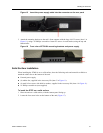
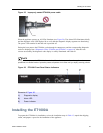
1 Check that the power supply cable is properly inserted in the power connector on the ETEP rear
panel. The ET0010A is shown in Figure 21.
2 Plug the power cord into the ETEP power supply. Attach the opposite end to a power source to apply
power to the appliance.
When the appliance powers up, all LEDs illuminate. The power LED remains lit until the unit is powered
off.
During the boot process the ETEP cycles through its startup tests, and the corresponding status LEDs are
illuminated (see “Status Codes: ET0010A” on page 63). After the tests execute successfully, the status
indicators turn off.
NOTE
During the boot process the ETEP discards all traffic on its data ports. Once the appliance is operational,
the default mode of operation passes all packets in the clear until you deploy security policies.
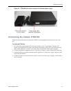
Installing the ET0100A
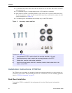
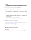
To prepare the ET0100A for installation, review the installation steps in Table 13, unpack the shipping
carton, and prepare a space for the installation of the appliance.
The steps to perform for a typical installation are listed below.
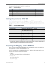
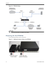
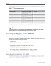
Cabling Requirements: ET0100A
Table 14 outlines the standard cables used with each port on the ET0100A. The connector type listed
indicates only what is required to connect to the ET0100A port, and may or may not be the same
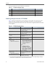
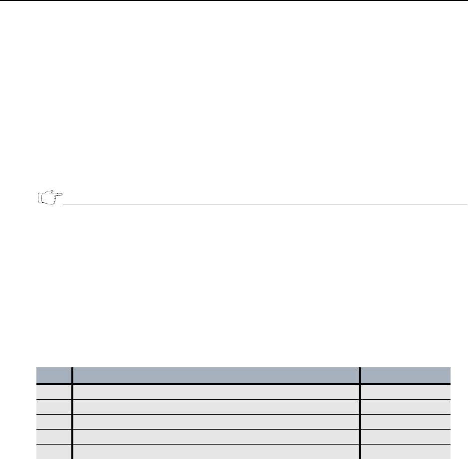
Table 13 ET0100A Installation Steps
Step Action to Perform Description
1 Review the cabling requirements. on page 35
2 Unpack the shipping package. on page 36
3 Prepare a space for installation of the ET0100A. on page 36
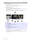
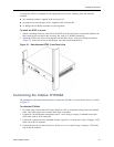
4 Connect the cables. on page 37
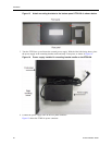
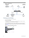
5 Apply power to the ET0100A. on page 38