


Installing the ET1000A
ETEP Installation Guide 39
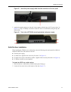
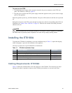
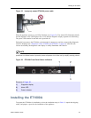
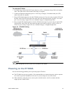
Figure 25 Improperly seated ET0100A power cable
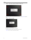
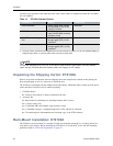
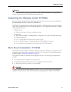
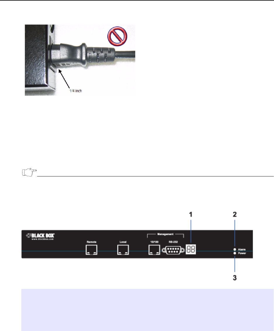
When the appliance powers up, all LEDs illuminate (see Figure 26). The Alarm LED illuminates briefly
and the diagnostic code LED displays 88 to verify that the diagnostic display segments are functioning.
The power LED remains lit until the unit is powered off.
During the boot process the ET0100A cycles through its startup tests, and the corresponding diagnostic
codes are displayed (see “Diagnostic Codes: ET0100A and ET1000A” on page 64). After the tests
execute successfully, the diagnostic code display is solidly illuminated with code 00.
NOTE
During the boot process the ET0100A discards all traffic on its data ports. Once the appliance is
operational, the default mode of operation passes all packets in the clear until you deploy security policies.
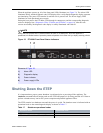
Figure 26 ET0100A Front Panel Status Indicators
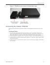
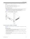
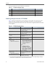
Installing the ET1000A
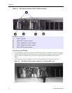
To prepare the ET1000A for installation, review the installation steps in Table 15, unpack the shipping
carton, and prepare a space for the installation of the appliance.
Elements of Figure 26:
1) Diagnostic display
2) Alarm LED
3) Power indicator