


Chapter 3: Installation
724-746-5500 | blackbox.com
Page 17
3.3.5 Optional LED indicator connections
The optional ServSwitch Freedom LED Monitor module (part number: KV0004A-LED) enables you to add LED (Light Emitting
Diode) indicators to each of your video display screens to show which are active.
Note: The ServSwitch Freedom switch requires firmware version 2.0 or later to be installed. Please see 4.7 Performing
upgrades for details about how to check.
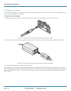
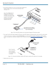
The optional ServSwitch Freedom LED Monitor module connects to the OPTIONS port of the main ServSwitch Freedom switch.
Each individual LED monitor indicator then connects to one of the ten ports on the ServSwitch Freedom LED Monitor module.
Notes: The ServSwitch Freedom LED Monitor module MUST be connected before the switch is powered on, otherwise the mod-
ule will not be recognized. Also, if the module is temporarily disconnected from the switch during operation, communication
between the two will cease and the switch will need to be re-powered with the ServSwitch Freedom LED Monitor module
attached.
Before operation of the LED indicators can occur, it is necessary to temporarily connect the ServSwitch Freedom switch to a
Windows computer. This will allow you to use the Glide and Switch application to program the required operation of the switch.
Please see 4.5 Configuring LED indicators for details about using the Glide and Switch configuration application.
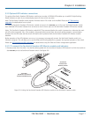
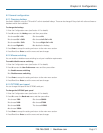
3.3.5.1 To connect the ServSwitch Freedom LED Monitor module and indicators
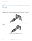
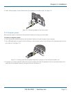
1. Remove power from the switch. Use the flat cable supplied with the ServSwitch Freedom LED Monitor kit to link the module to
the OPTIONS port of the ServSwitch Freedom switch. See Figure 3-9.
Link cable
(Included in ServSwitch
Freedom LED Monitor kit)
ServSwitch
Freedom LED
Monitor module
Figure 3-9. Linking the ServSwitch Freedom LED Monitor module to the ServSwitch Freedom switch.