


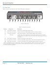

ServSwitch Freedom
724-746-5500 | blackbox.com
Page 18
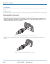
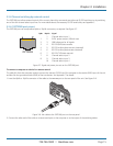
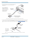
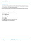
2. Link each LED indicator to a port on the ServSwitch Freedom LED
Monitor module - ports 1 to 4 are most commonly used.
See Figure 3-10.
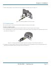
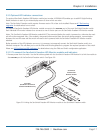
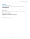
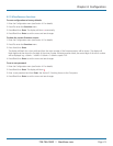
3. You need to tell the ServSwitch Freedom LED Monitor which LED indicator to illuminate (and in which color) for each channel.
To do this connect your computer to the TO KEYPAD OR PC port of the ServSwitch Freedom LED Monitor module (while it
remains connected to the ServSwitch Freedom switch). Please see the section 4.5 Configuring LED indicators. See Figure
3-11.
LED indicator with
3 metre lead
Port 2
Port 3
Port 4
Insert the lead for
the first indicator
into port 1
Each indicator has a self adhesive
Velcro tab to assist with mounting
on your video displays.
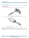
Flash upgrade cable
(Included in
ServSwitch Freedom
LED Monitor kit)
Connect to a vacant
serial port on your
computer
Note: If required,
the PC connection
can be removed
once programming
is complete.
Figure 3-10. Linking LED indicators to the ServSwitch Freedom LED Monitor module.
Figure 3-11. Linking the ServSwitch Freedom LED Monitor module to the serial port of a computer.
4. Apply power to the switch.
Note: The KV0004A-LED kit
includes four LED indicator
assemblies. Up to ten can be
connected and additional LED
indicators can be ordered
using the part number:
KV0004A-XTRA-LED.